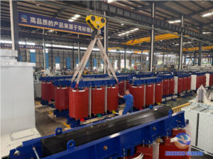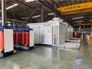
Pick up almost any transformer nameplate and, somewhere near the rated capacity and voltage, you’ll find a short code like Dyn11, Yyn0, or YNd11. To someone outside the industry it looks like a part number. To an engineer, it’s one of the most important lines on the plate — it tells you exactly how the winding is built, whether a neutral is available, and whether this unit can safely run in parallel with another. This guide walks through what those letters and numbers actually mean, using real nameplates from transformers we manufacture as examples.
Two Basic Winding Connections: Star and Delta
Every vector group, no matter how it’s written, is built from just two basic ways of connecting a three-phase winding: star and delta.
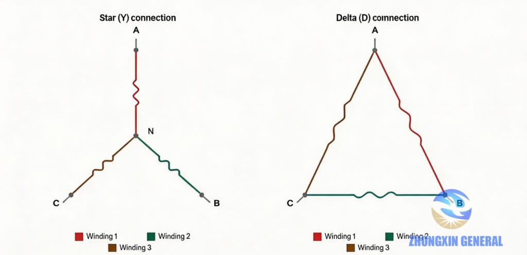
Star (Y or y) connection joins one end of all three windings together at a common point — the neutral — while the other three ends are brought out as the line terminals. Because each winding only carries the “phase” voltage rather than the full line voltage (about 57.7% of it), insulation requirements are lower, which is one reason star connections are common on the high-voltage side of a transformer. The real advantage of star, though, is the neutral point itself: bring it out and you can supply both three-phase and single-phase loads from the same winding — the basis of any 3-phase-4-wire distribution system.
Delta (D or d) connection connects the windings end-to-end in a closed loop, with the three line terminals sitting at the corners of the triangle. There’s no neutral point to bring out, so delta only ever supplies three-phase power directly. What delta does very well is contain third-harmonic currents: they can circulate inside the closed loop instead of leaking onto the supply network, which keeps the voltage waveform cleaner. Winding current is also lower than line current, so delta windings can use somewhat lighter conductor for the same rating.
Every vector group you’ll ever see on a nameplate is just some combination of these two connections on the high-voltage and low-voltage sides.
Reading a Vector Group: Letters, Then a Clock Position
Vector group notation follows a simple convention once you know the rule.
Capital letters describe the high-voltage winding; lowercase letters describe the low-voltage winding.
| Symbol | Meaning |
|---|---|
| Y / y | Star connection |
| YN / yn | Star connection, with the neutral point brought out |
| D / d | Delta connection |
| Z / z | Zigzag connection (a special star variant) |
The number describes the phase-angle displacement between the two windings, using clock notation. Imagine the high-voltage line voltage as the minute hand of a clock, fixed at 12. The low-voltage line voltage is the hour hand — wherever it points is the number in the vector group. “11,” for example, means the low-voltage side leads the high-voltage side by 30°.
Put the two pieces together and you get a complete code — Dyn11 is a delta-connected HV winding, a star-connected LV winding with the neutral brought out, and a 30° phase shift.
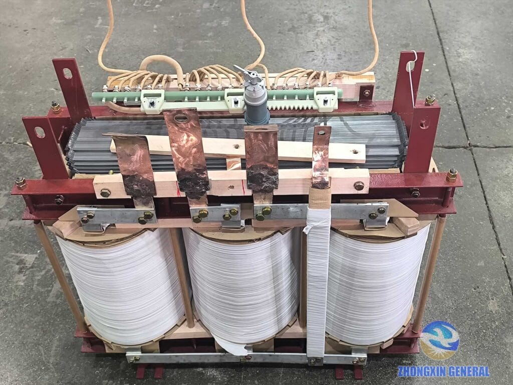
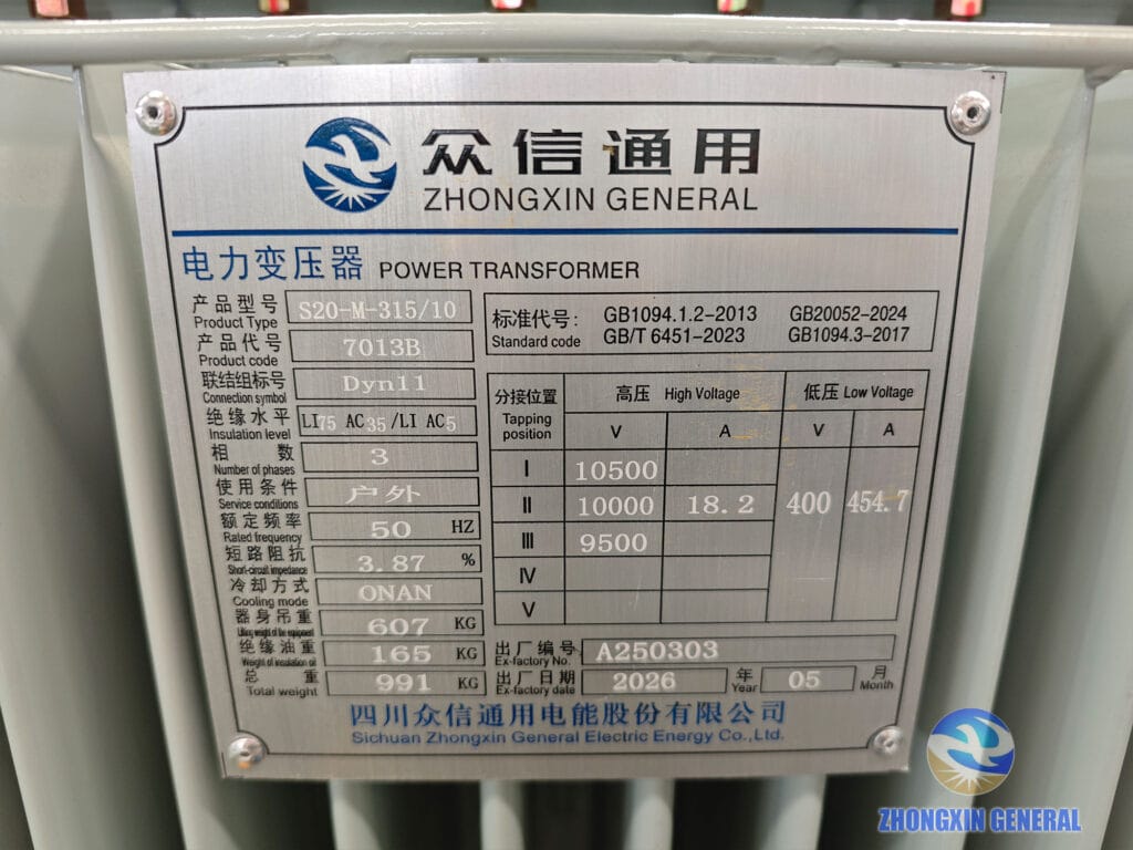
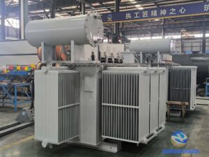
This pattern holds across capacities and cooling types — our 315 kVA oil-immersed distribution transformer : HV delta connection, LV star connection with neutral lead-out and Dyn11 marking on the nameplate. The only difference is its smaller overall structure and oil cooling mode.
Four Basic Combinations, Then the Details
Once you know that HV and LV can each be either star or delta, there are only four basic pairings to start from:
| Combination | HV Winding | LV Winding |
|---|---|---|
| Y,y | Star | Star |
| D,y | Delta | Star |
| Y,d | Star | Delta |
| D,d | Delta | Delta |
Every specific vector group you’ll see on a nameplate is one of these four pairings, refined by two more details: whether the neutral point is brought out (adding an “N” to the HV side or an “n” to the LV side), and the exact phase-angle displacement, given as a clock number. Add those two layers to “D,y” and you get, for example, Dyn11 — delta HV, star LV with the neutral brought out, 30° displacement.
The Vector Groups You’ll Actually Encounter
Dyn11 — the default for modern distribution transformers. Delta on the HV side, star with neutral on the LV side, 30° displacement. The delta HV winding gives third-harmonic currents a closed loop to circulate in, which is the main reason Dyn11 tolerates unbalanced and single-phase-heavy loads far better than an equivalent Yyn0 design, and why it has become the standard recommendation in most national and international specifications for 10 kV-class distribution transformers.
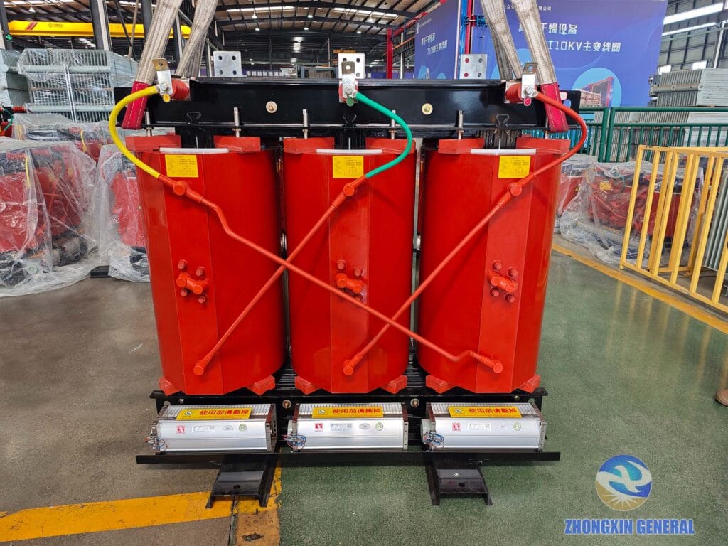
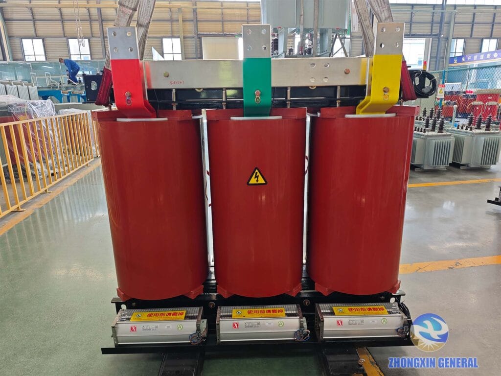
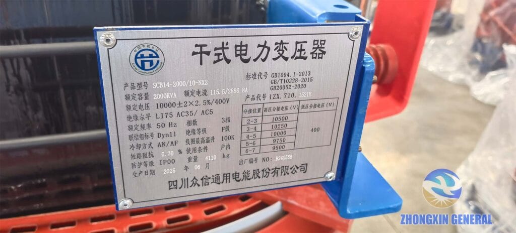
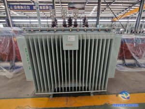
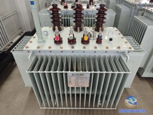
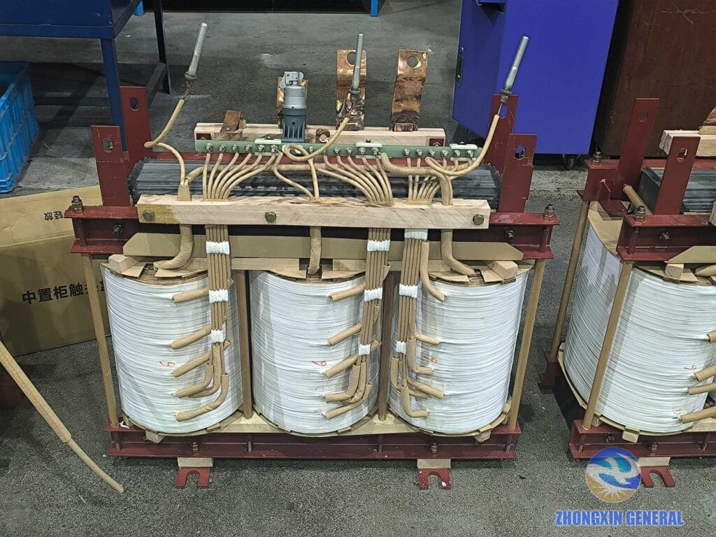
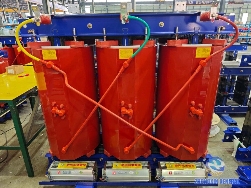
The photos above are from an actual 2000 kVA cast resin dry-type transformer we manufacture — the delta HV connection, the star LV connection with neutral, and the nameplate that ties both back to the Dyn11 code stamped on it.
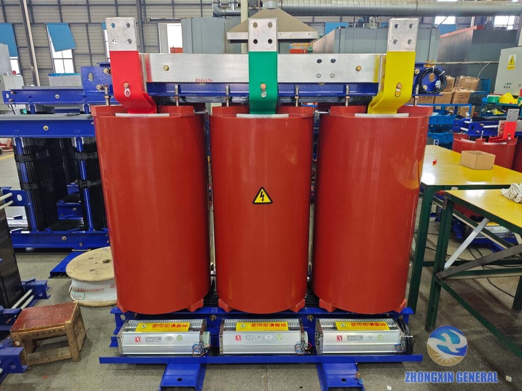
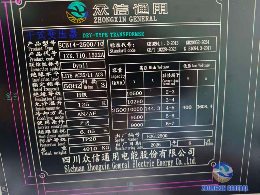
The same is true further up the range, on our 2500 kVA cast resin dry-type transformer — Dyn11 scales comfortably from a few hundred kVA up to several thousand.
Yyn0 — the older, simpler alternative. Star on both sides, neutral brought out on the LV side, no phase displacement. It’s cheaper to build because there’s no need to insulate a delta winding, and it works fine where the three-phase load stays reasonably balanced. Its weak point is exactly where Dyn11 is strong: without a delta winding to absorb third-harmonic currents, a Yyn0 unit is more limited in how much single-phase, unbalanced load its neutral can carry before waveform quality and neutral-point stability start to suffer.
Yd11 — star HV, delta LV. Common on medium-voltage transmission and step-down transformers where the low side doesn’t need to supply single-phase loads directly. The delta LV winding still delivers the harmonic-suppression benefit, improving the voltage waveform seen further upstream.
YNd11 — star HV with the neutral grounded, delta LV. This is the connection you’ll find on larger, higher-voltage transformers, because bringing out and grounding the HV neutral is exactly what large solidly-grounded transmission networks require for protection and fault-clearing.
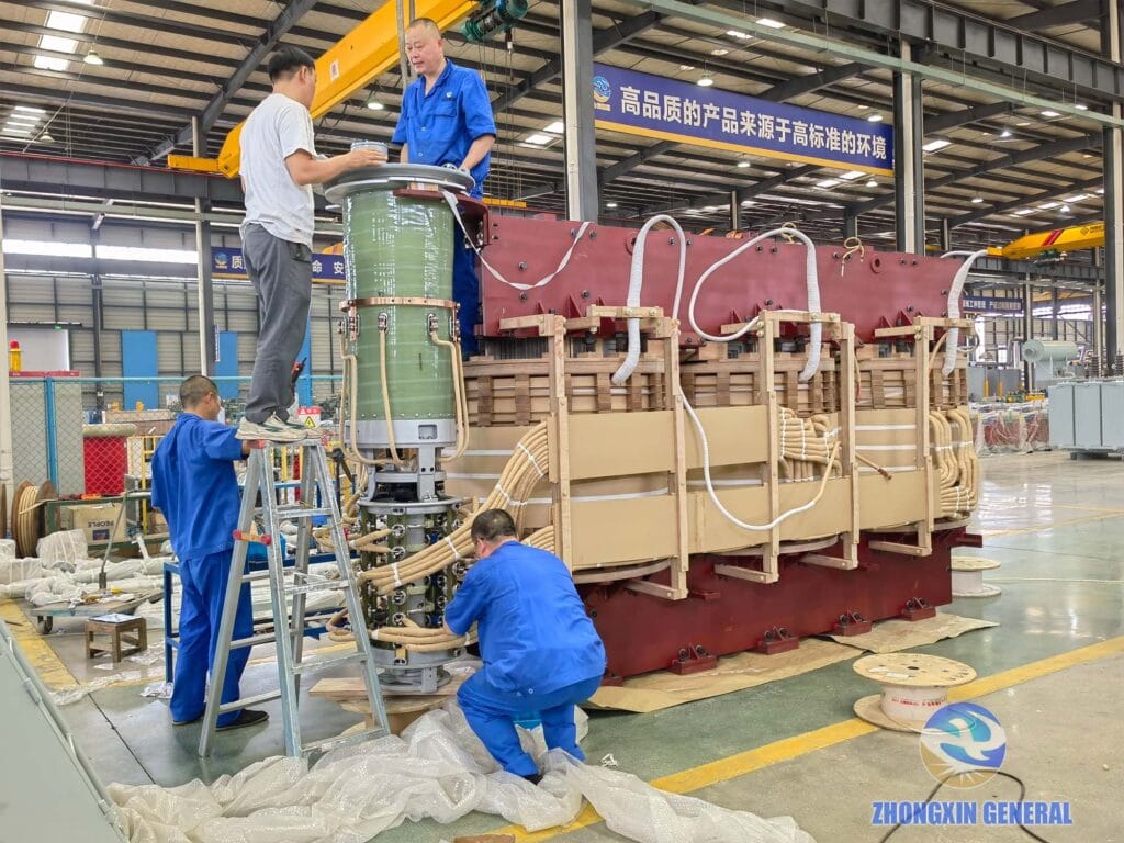
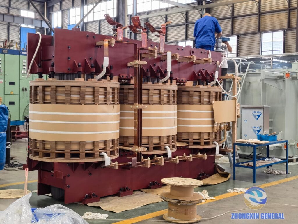
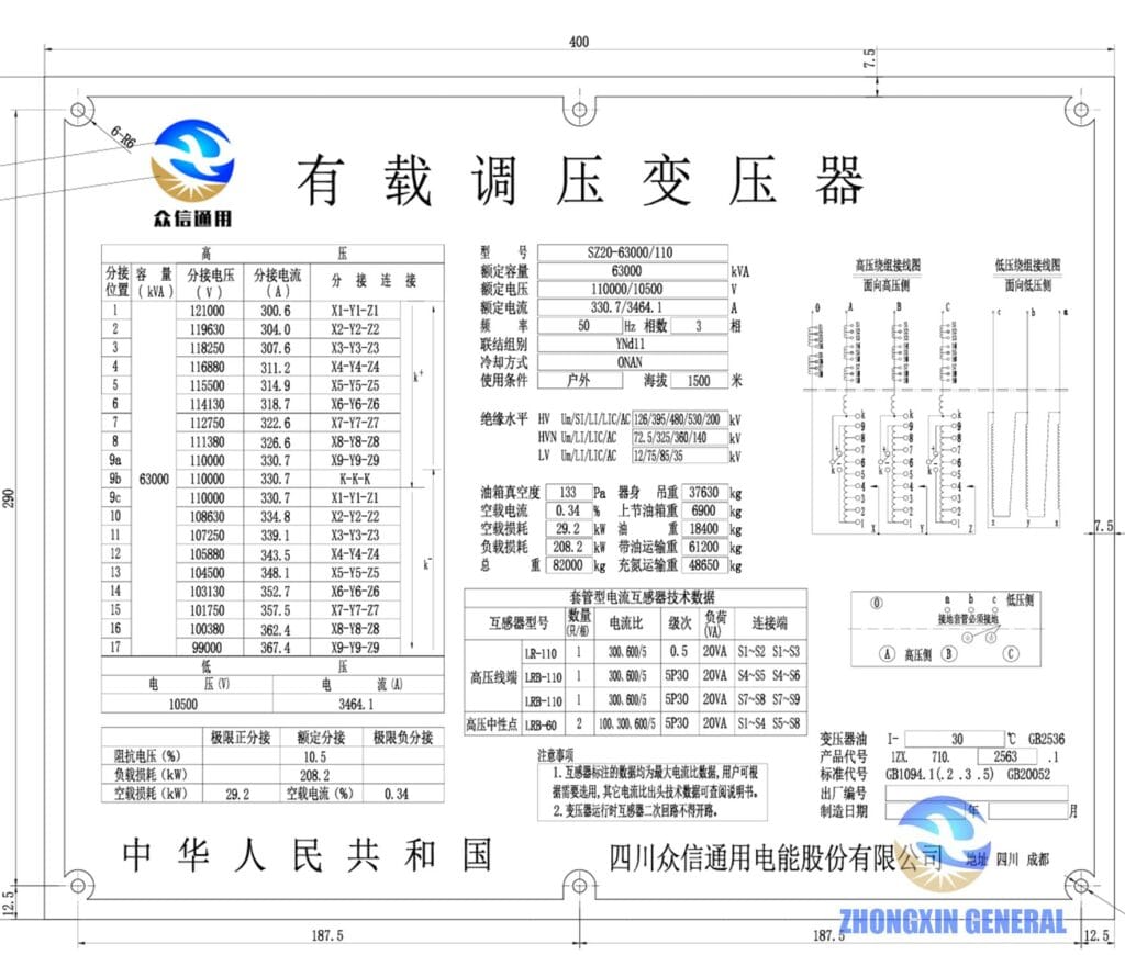
At the other end of the scale, our 63,000 kVA OLTC power transformer is a good example of YNd11 in practice: a 110 kV star winding with the neutral brought out and grounded, stepping down to a 10.5 kV delta winding — the configuration expected on transformers of this class.
Vector Groups and Parallel Operation
If you’re expanding a substation by adding a second transformer to run alongside an existing one, the vector group is not a detail you can round off — it’s a hard requirement. Two transformers can only be paralleled if their vector groups match exactly. A 30° phase mismatch between, say, a “0” group and an “11” group creates a large circulating current between the units the moment they’re connected in parallel, which can damage windings very quickly. Beyond matching vector groups, a safe parallel connection also needs matching voltage ratios, impedance values within roughly 10% of each other, and rated-capacity ratios that aren’t too far apart (commonly kept under about 3:1).
Choosing the Right Vector Group
A few practical questions usually settle it:
- Do you need single-phase output as well as three-phase? If so, the LV side needs a star connection with the neutral brought out.
- Does the HV neutral need to be grounded? This points toward a YN-type HV winding, typical at 110 kV and above.
- How balanced is the load, and how much harmonic-generating equipment (VFDs, rectifiers, etc.) is on the network? The less balanced and the more harmonic-heavy, the stronger the case for a delta HV winding — i.e., Dyn11.
- What voltage class are you working at? As a rough guide, Dyn11 dominates at 10 kV distribution level, Yd11 is common in the 35–66 kV range, and YNd11 is typical at 110 kV and above.
Summary
| Vector Group | HV Winding | LV Winding | Phase Shift | Typical Use |
|---|---|---|---|---|
| Dyn11 | Delta | Star + neutral | 30° | Distribution transformers, unbalanced/single-phase-heavy loads |
| Yyn0 | Star | Star + neutral | 0° | Simple distribution, balanced loads, older/legacy designs |
| Yd11 | Star | Delta | 30° | Medium-voltage step-down (35–66 kV class) |
| YNd11 | Star + neutral | Delta | 30° | High-voltage transformers (110 kV and above) |
Once you can separate “which two connections are combined” from “how far apart their phase angles are,” any vector group on a nameplate stops being a mystery. Dyn11 is the connection you’ll see on the large majority of new distribution transformers today, largely because of how well it handles the unbalanced, harmonic-rich loads common in real installations — but Yyn0, Yd11, and YNd11 each still have a legitimate place depending on voltage class and grounding requirements.
For a closer look at how these connections show up on real, delivered equipment, browse our case studies and company news archives, or see the full technical datasheets for the 315 kVA, 2000 kVA, 2500 kVA, and 63,000 kVA units referenced above.
About Zhongxin General
Zhongxin General (Sichuan Zhongxin General Electric Energy Co., Ltd.) is a China-based manufacturer of oil-immersed and dry-type power transformers, HV/MV/LV switchgear, and prefabricated substations, headquartered in Xinjin District, Chengdu. Our product range includes dry-type power transformers, from 30 kVA to 20 MVA with voltage ratings up to 35 kV, and oil-immersed power transformers, from 30 kVA to 100 MVA with voltage ratings up to 110 kV, is built and routine-tested in-house, with the vector group verified as part of standard factory acceptance testing before dispatch.