Every transformer, no matter its size or voltage class, exists because engineers spent nearly a century and a half solving one problem: how to carry a magnetic field back and forth without wasting most of it as heat, noise, and wasted copper. That problem lives in the core — the stack of steel or alloy at the center of every transformer — and its history is really a story about squeezing loss out of iron, one material breakthrough at a time.
This article walks through that evolution: from the first laminated wrought-iron core built at Ganz Works in 1884, through hot-rolled and grain-oriented silicon steel, to today’s amorphous and nanocrystalline alloys. Along the way we’ll also look at how core structure — lamination joints, stacking methods, wound cores — evolved alongside the materials, and what any of this has to do with the transformer sitting on your project site today.
The First Commercial Core: Laminated Wrought Iron (1884–1902)
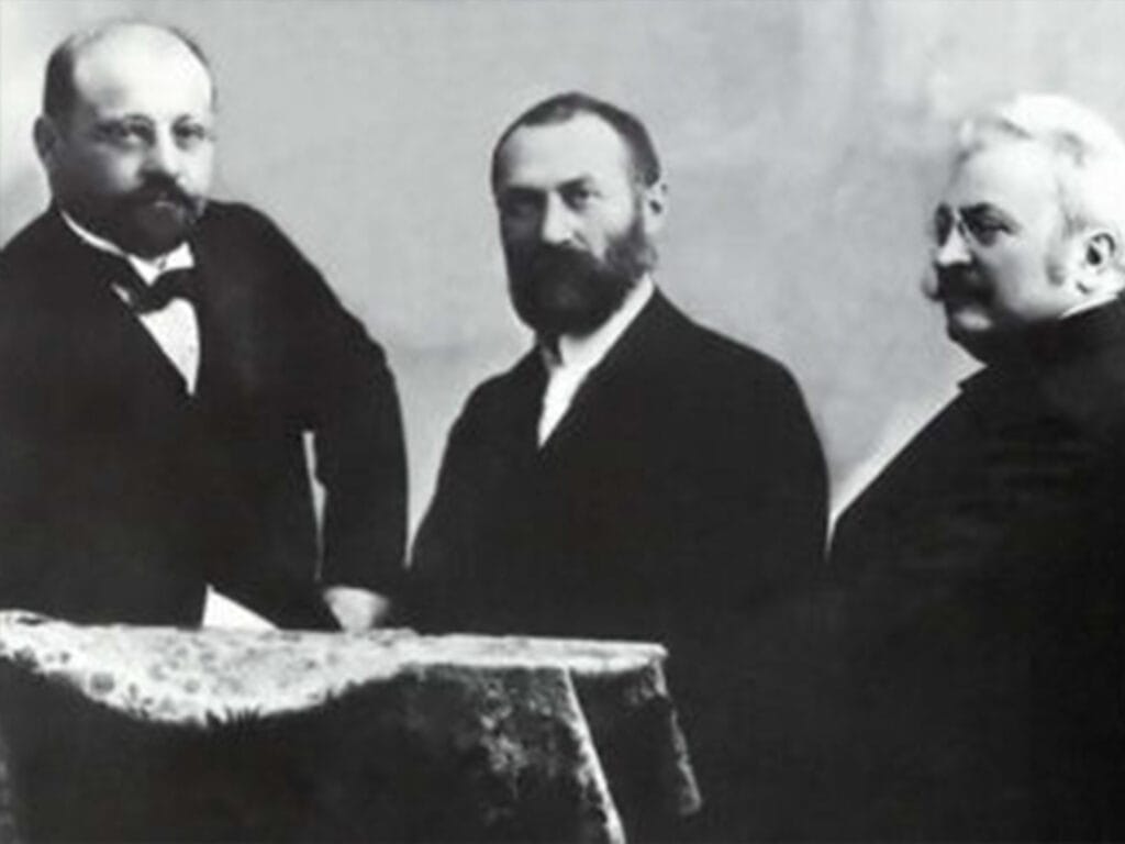
The breakthrough came in 1884–1885 at Ganz Works in Hungary. Engineers Károly Zipernowszky, Ottó Bláthy, and Miksa Déri built the ZBD transformer — the first device with a segmented, laminated, closed magnetic core, publicly demonstrated at the 1885 Budapest Electrical Exhibition. It was also the device that gave the industry its name: “transformer.”
The material was still low-carbon wrought iron with no silicon added. The real innovation was structural: instead of one solid block, the core was built from thin, hand-stacked, insulated iron sheets that dramatically suppressed eddy currents. Early shapes were rectangular or simple bent rings, with wide joints and high magnetic reluctance.
Refinements followed quickly. Sebastian Ferranti introduced a circular bent-lamination core in 1888, improving on the rectangular shape for early high-voltage transmission transformers. In the US, Westinghouse — under the direction of William Stanley — standardized the E-I lamination in 1886, which became the production backbone of distribution transformers for decades.
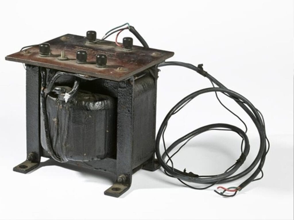
But pure iron has a hard ceiling: high hysteresis loss and low resistivity mean heavy, hot-running units. That ceiling capped how large a single transformer could get, which in turn capped how far AC power could be economically transmitted.
The First Material Revolution: Hot-Rolled Silicon Steel (1903–1933)
Between 1889 and 1900, British metallurgist Robert Hadfield and his team found that adding roughly 1–4% silicon to low-carbon iron raises resistivity, lowers hysteresis loss, and eliminates magnetic aging — silicon suppresses eddy currents by raising resistivity while also reshaping the iron’s crystal structure to shrink the hysteresis loop.
By 1903, the US and Germany were mass-producing hot-rolled silicon steel (sold under names like “Stalloy”), replacing wrought iron outright. Because it was hot-rolled, the grain structure was randomly oriented — but even so, no-load losses fell by more than 50%, and core volume and weight for the same rating shrank by around 30%. Russia adopted it by 1915, Japan by 1924, and it became the global standard.
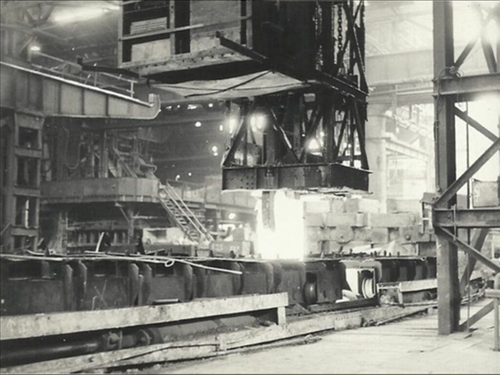
Lamination shapes stayed largely E-I and three-limb, hand-cut with fairly crude interlaminar varnish. The inherent flaw was directionality: with randomly oriented grains, magnetic performance along the rolling direction differed sharply from the transverse direction, and at 0.35–0.5mm thickness, losses were still relatively high. Hot-rolled steel was gradually phased out starting in the 1960s.
Cold-Rolled Grain-Oriented Steel and the 45° Joint (1934–1963)
The next leap came from Norman P. Goss at Armco in the US. Between 1933 and 1935, Goss developed a double cold-rolling process combined with high-temperature secondary recrystallization, producing 3% silicon steel with grains aligned along the rolling direction (deviation of 7° or less) — a crystal texture still known today as “Goss texture.” Armco partnered with Westinghouse to bring cold-rolled grain-oriented steel (CRGO) to market in 1935.
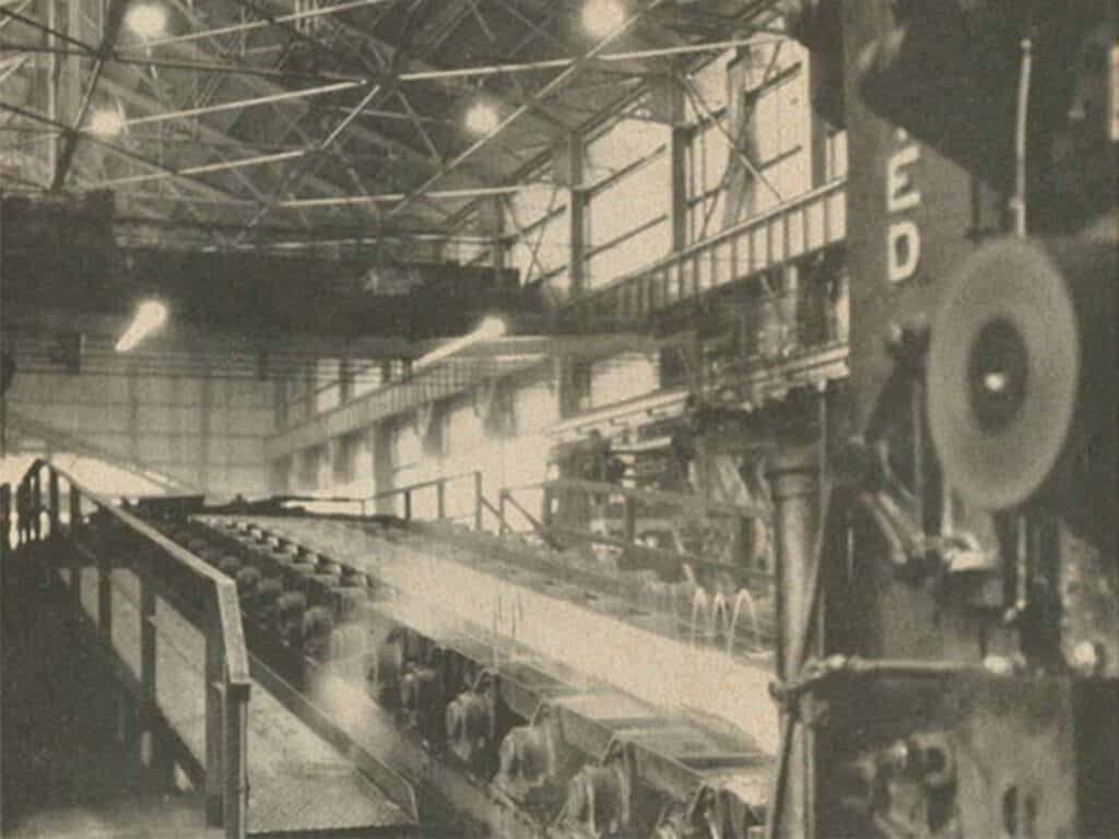
CRGO reshaped core design as much as it reshaped the material. Because the steel’s high permeability now ran in one direction, core joints shifted to a 45° mitred cut instead of a straight butt joint, cutting joint losses by around 40%. Manufacturing shifted from hand assembly to slitting lines, and hole-free clamping (using tensioned glass tape instead of bolted holes) removed flux-shorting points from the core altogether.
The result: losses fell to roughly a third of hot-rolled steel, letting manufacturers build much larger power transformers and HV mains units. CRGO capacity became strategically important enough that, after WWII, US exports of the material were briefly export-controlled.
HiB Steel: The Race Toward Lower Losses (1964–1980)
In 1964, Nippon Steel (now Nippon Steel Corporation) introduced HiB — high-permeability grain-oriented steel — by tightening grain deviation to 3° or less and adding a high-tension glass coating that compresses magnetic domain width. The result was a further 30–40% cut in core loss, with typical performance around 0.92 W/kg at 50Hz/1.7T.
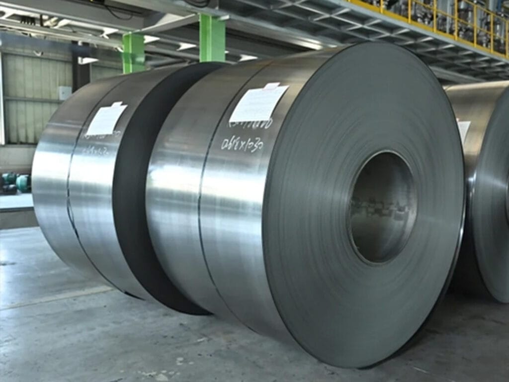
HiB coil went global in 1968, and Japan effectively dominated the high-grade silicon steel supply chain for years; hot-rolled steel production stopped worldwide around this time. On the manufacturing side, stepped-lap and full-diagonal joints became standardized, and early experimentation began with three-phase five-limb cores and wound-core construction.
Domain Refinement and Ultra-Thin Steel (1980–2000)
By the 1980s, engineers were laser- and plasma-scribing fine scratches into HiB strip to artificially divide wide magnetic domains — narrower domains mean less eddy-current loss when domain walls move, so the scribing effectively “pins” the domain structure. This pushed losses down to around 0.6 W/kg at 50Hz/1.5T, close to the practical ceiling for silicon steel.
Ultra-thin 0.27mm and 0.23mm CRGO followed, aimed at UHV and large converter-transformer applications where every fraction of a watt matters. On the structural side, wound (step-lap) cores — a continuous strip wound with essentially no butt joints — cut noise and loss further and became especially common in dry-type transformers, where compact, low-noise designs are prized.
Amorphous and Nanocrystalline Cores: The Low-Carbon Era (1974–Present)
The most recent material leap doesn’t use crystalline steel at all. Amorphous metal — typically an iron-silicon-boron alloy such as Fe₇₈Si₉B₁₃, commercially known as Metglas — is produced by quenching molten alloy at roughly 1,000,000°C per second using a single-roller rapid-cooling process. The atoms freeze in a disordered arrangement with no grain boundaries and essentially no magnetocrystalline anisotropy, giving it soft-magnetic performance well beyond silicon steel.
Key milestones: Allied Chemical (later Allied-Signal, now part of Honeywell) achieved mass production of iron-based amorphous alloy in 1974; the first 10kVA amorphous-core distribution transformer appeared in 1978; and from the 1980s, Hitachi Metals licensed Metglas technology to become a major Asian ribbon supplier.
Core loss for amorphous alloy runs at roughly a quarter to a fifth of HiB steel — around 0.28 W/kg at 1.5T/50Hz — a dramatic cut in no-load loss that suits high-efficiency distribution transformers well. The trade-off is that the ribbon is only 25–30μm thick, brittle, and has a lower stacking factor (about 0.8 versus 0.95+ for silicon steel), with higher material cost — which is why amorphous cores stay concentrated in small and mid-size distribution transformers rather than large power units.
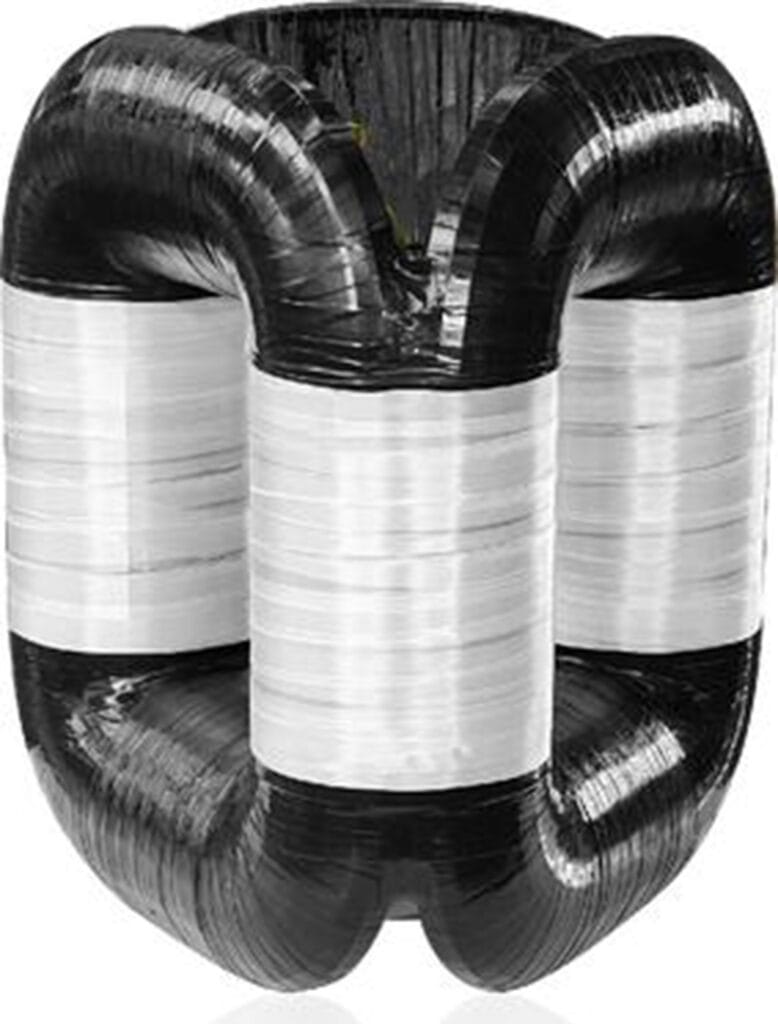
Since the 2000s, nanocrystalline cores have carved out their own niche: low-temperature annealing (typically 500–550°C) of amorphous ribbon precipitates 10–20nm grains, combining high saturation flux density with very low high-frequency loss. These are used mainly in solar inverters, wind converters, EV chargers, and other power-electronic transformers rather than standard 50/60Hz power transformers.
The Parallel Story: Core Structure and Manufacturing
Material tells you what the core is made of; structure tells you how efficiently that material gets used. The two threads run independently but constantly push each other forward.
Core-type vs. shell-type. By the mid-1880s, two basic layouts had emerged. In core-type construction — used in the original ZBD transformer — the windings surround the core limb; it’s simple, cools well, and remains the dominant layout for power transformers. In shell-type construction, pioneered by William Stanley at Westinghouse, the core surrounds the windings instead, giving higher mechanical strength and lower leakage flux, which suits large or specialized units. Neither is strictly better; the right choice depends on rating, voltage class, and application — much like the choice between vector groups depends on the system it serves.
Joint evolution. Butt joints (simple but high-reluctance and noisy) gave way to interleaved lap joints in the early 1900s, then to 45° mitred joints once CRGO made directional alignment worthwhile from the 1940s onward, then to stepped-lap and multi-stage mitred joints from the 1960s that pushed joint losses toward their practical floor.
Cross-section. Early core limbs were simple rectangles or crosses; from the mid-20th century, multi-step, near-circular cross-sections became standard, lifting material utilization from around 75% to over 90%.
Wound cores. From the 1960s, and mainstream from the 1980s, some cores are built by continuously winding a single strip rather than stacking individual sheets — nearly eliminating joints and simplifying automation for small and mid-size distribution transformers, at the cost of the disassembly flexibility that stacked cores offer.
Noise and vibration. From the 1970s, as urban distribution transformers faced tighter noise limits, core design also had to solve magnetostriction-driven vibration directly — through low-magnetostriction CRGO, optimized joint stress, and elastic core clamping — a design goal that runs alongside, but separately from, loss reduction.
Why Core Material Still Matters When You Specify a Transformer
None of this history is just trivia if you’re the one buying the transformer. Core material and construction drive no-load loss, which runs 24/7 regardless of demand — over a transformer’s service life, that steady loss can matter more to total cost of ownership than the purchase price itself. It’s one of several specifications worth locking down before you request a quote; our transformer parameter checklist walks through the others. And if you’re still deciding between core types entirely, our comparison of dry-type vs. oil-immersed transformers is a good next stop.
A Closing Thought
From a hand-stacked wrought-iron core that ran hot and heavy, to amorphous ribbon that loses a twenty-fifth as much energy per kilogram, transformer core technology has spent a century and a half chasing the same three goals: less hysteresis loss, less eddy-current loss, and less material for the same output. Two threads drove that progress — metallurgy (wrought iron → hot-rolled silicon steel → grain-oriented steel → amorphous → nanocrystalline) and structural engineering (solid → laminated → mitred-jointed → wound cores) — and they’ve always had to advance together, since a new material rarely pays off without a new way to build it into a core.
Want to see how these principles apply to a project of your own? Browse our case studies for real transformer and substation deliveries, or get in touch with our team.
Supplementary table
| Material | Main Era | Typical Loss (W/kg, approx.) | Loss vs. Wrought Iron |
|---|---|---|---|
| Wrought / soft iron | 1831–1902 | ~7–10 | 1× (baseline) |
| Hot-rolled silicon steel | 1903–1963 | ~3–4 | ~1/2 |
| Cold-rolled grain-oriented (CRGO) | 1934–1963 | ~1.3–1.5 | ~1/6 |
| HiB high-permeability steel | 1964– | ~0.92 | ~1/8 |
| Laser-scribed ultra-thin steel | 1980– | ~0.6 | ~1/12 |
| Iron-based amorphous alloy | 1978– | ~0.28 | ~1/25 |