Abstract
Transformers constitute the core power infrastructure of electric vehicle (EV) charging stations, directly governing power supply stability, charging efficiency, equipment service life, operational cost control, and future expansion flexibility. Most common charging station faults, including frequent tripping, voltage fluctuation, excessive harmonic distortion, and failed capacity expansion, originate from improper transformer sizing. Combined with frontline engineering experience and standardized electrical specifications, this guide presents a fully practical, step-by-step transformer sizing workflow tailored for EV charging station projects. It serves as a reliable technical reference for project investors, design engineers, construction teams, and operation and maintenance personnel worldwide.
1. Operational & Economic Losses Caused by Improper Transformer Sizing
Incorrect transformer configuration introduces persistent operational risks and irreversible economic losses for EV charging projects. The most frequent sizing errors and their practical consequences are summarized below.

1.1 Insufficient Transformer Capacity
Undersized transformers trigger frequent overload tripping during peak charging hours, forcing charging piles to derate output power and resulting in user churn and reduced station revenue. Capacity expansion renovation requires high retrofitting costs and prolonged operational suspension. For heavy-duty truck charging stations with severe capacity shortages, even 120kW high-power charging piles may drop to merely 30kW output, drastically suppressing operational profitability.
1.2 Excessive Capacity Oversizing
Overcapacity mismatch — deploying large-capacity transformers for low actual loads — leads to long-term light-load operation, elevated basic electricity fees, and excessive no-load losses, significantly extending the investment payback period. In practical cases, some charging stations adopt 1250kVA transformers operating at only 35% load rate, incurring additional annual power costs of over $11,000.
1.3 Inappropriate Transformer Model Selection
Oil-immersed transformers applied in underground garage charging stations will fail fire safety and official acceptance standards. Ordinary epoxy resin dry-type transformers deployed at heavy-duty truck charging stations are prone to coil fatigue and premature failure due to long-term impact load cycling.
1.4 Neglected Critical Electrical Parameters
Ignoring harmonic resistance and impedance voltage parameters causes voltage flicker, power quality degradation, and intermittent restart faults of charging equipment. It is essential to distinguish between kW (active power) for charging pile output and kVA (apparent power) for transformer rated capacity. Accurate sizing relies on comprehensive calculation based on demand coefficients, simultaneous utilization factors, and economic load rates, rather than simple power summation of all charging piles.
2. Four Core Principles of EV Charging Station Transformer Sizing
2.1 Load Matching Principle
Accurately calculate actual operating loads based on charging equipment types (DC fast charging / AC slow charging), project scenarios, and user charging behavior, avoiding energy waste from long-term light-load operation and equipment faults caused by overload operation.
2.2 Future Expansion Redundancy Principle
EV charging stations are long-term operational assets. A reserved capacity margin of 10%–20% is mandatory to accommodate future charging pile upgrades and high-power ultra-fast charging iterations, eliminating the need for short-term secondary capacity expansion and retrofitting.
2.3 Safety & Compliance Principle
Strictly comply with on-site environmental constraints, fire protection codes, and grid access specifications. Prioritize transformers with superior harmonic resistance, overload tolerance, and explosion-proof performance to fully meet power grid acceptance and operational safety standards.
2.4 Economic Operation & Maintenance Principle
Select low-loss, low-noise and maintenance-free transformer models to balance initial procurement cost and long-term energy consumption & operation cost, maximizing the overall profit of charging station projects.
3. Pre-Sizing Site Data Investigation
Accurate field data collection is the prerequisite for precise transformer sizing, as all collected parameters directly determine the final capacity and model configuration scheme.

3.1 Basic Equipment Parameter Statistics
Count the total quantity of charging piles, single-unit rated power (7kW AC slow charging; 60kW/120kW/240kW/480kW DC fast charging), rated operating voltage, and power factor of all on-site power equipment.
3.2 Scenario Classification & Simultaneous Utilization Factor
Different scenarios have distinct load characteristics, which are the core basis for capacity calculation:
- Residential community charging stations: Dispersed off-peak charging, large peak-valley load difference; simultaneous utilization factor: 30%–50%
- Commercial complex charging stations: Concentrated daytime charging demand; simultaneous utilization factor: 50%–60%
- Highway and service area stations: Dense vehicle energy supplementation, concentrated peak loads; simultaneous utilization factor: 70%–90%
- Bus and heavy-duty truck dedicated stations: Batch centralized night charging, high full-load operation probability; simultaneous utilization factor: 80%–95%
3.3 On-Site & Grid Access Conditions
Confirm installation environment (indoor / outdoor), available site space, fire protection grade, local power bureau grid access standards, and system voltage level (10kV/0.4kV).
4. Transformer Capacity Calculation (Core & Error-Prone Procedure)
Transformer capacity is rated in kVA (apparent power), while charging pile power is measured in kW (active power). Direct numerical conversion is prohibited. The final capacity must be calculated through comprehensive correction of simultaneous utilization factor, power factor, and economic load rate.
4.1 Standard Engineering Calculation Parameters
- Charging equipment power factor: 0.9–0.95 (unified to 0.9 for preliminary estimation)
- Optimal long-term economic load rate: 60%–80% (0.7–0.8 for conventional engineering calculation)
- Future expansion redundancy: 10%–20% capacity margin
Note: This method applies to preliminary scheme estimation. Formal construction drawing design and grid approval require additional correction for equipment conversion loss and original building distribution load with standardized coefficient selection.
4.2 Practical Engineering Calculation Case

Project Condition: Highway service area charging station equipped with 8 sets of 120kW DC fast charging piles
Total active power rating: 120kW × 8 = 960kW
Peak active load (80% simultaneous factor for highway scenarios): 960kW × 0.8 = 768kW
Theoretical transformer capacity corrected by power factor and economic load rate: approximately 1140kVA
Final capacity with 10% expansion redundancy: 1254kVA
Standard capacity matching: adopt 1250kVA standard transformer
4.3 IEC Standard Transformer Capacity Gears
315kVA, 400kVA, 630kVA, 800kVA, 1000kVA, 1250kVA, 1600kVA, 2000kVA. Always round up to standard gears and avoid non-standard customization.
5. Transformer Model Selection for EV Charging Station Scenarios
Select targeted transformer models according to site environment and load characteristics to balance safety, stability and economy. Zhongxin General’s full range of power transformers covers all mainstream models for charging station scenarios, with EU Tier 2 energy efficiency certification and stable operational performance.
| Transformer Model | Core Advantages | Applicable Scenarios | Prohibited & Not Recommended Scenarios |
|---|---|---|---|
| YB European Prefabricated Box Substation | Integrated turnkey solution, no dedicated distribution room required, rapid on-site installation, compact footprint | Highway stations, logistics parks, outdoor public charging stations | Closed underground indoor spaces |
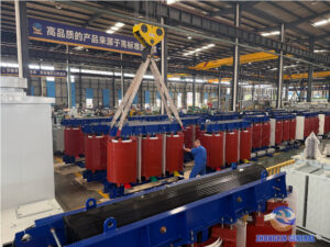
| SCB14 Epoxy Resin Dry-Type Transformer | Oil-free and flame-retardant, maintenance-free, high fire safety compliance, low operational loss | Indoor distribution rooms, community underground garages, commercial indoor charging stations | Not recommended for heavy-duty truck stations with long-term full-load impact operation |
| Wound Core Dry-Type Transformer | Strong impact load resistance, excellent heat dissipation performance, anti-crack coil design | Heavy-duty truck charging stations, outdoor sites with dust, salt fog, and extreme temperature differences | No absolute prohibition (higher initial procurement cost) |
| K13 Harmonic-Resistant Transformer | Effectively suppresses harmonic interference from charging piles, reduces coil overheating and power quality degradation | High-power dense fast charging stations and ultra-fast charging hubs | Unnecessary for small-scale scattered low-power charging piles |
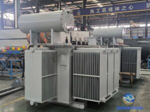
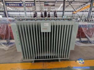
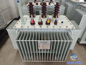
| Oil-Immersed Transformer | Strong overload capacity, cost-effective, mature and stable operational performance | Open outdoor suburban charging stations | Underground garages, indoor distribution rooms, densely populated areas |
6. Targeted Scheme Design for Typical Charging Station Scenarios
6.1 Residential Community Charging Stations (7kW AC Slow Charging Dominant)
Load Characteristics: Decentralized off-peak night charging, low full-load operation probability. Most existing community distribution transformers operate at 40%–60% load rate with sufficient residual capacity, eliminating the need for overall transformer replacement in most renovation projects.
Sizing Scheme: Adopt SCB14 high-efficiency dry-type transformers for indoor distribution rooms; deploy YB outdoor box substations for newly added charging capacity (ground installation only, strictly prohibited in closed underground spaces).
Operation Optimization: Equip valley-period ordered charging management systems to balance peak-valley load distribution and improve existing power asset utilization.
6.2 Urban Public Fast Charging Stations (120–180kW DC Piles)
Apply a simultaneous utilization factor of 0.5–0.7 and economic load rate of 0.75–0.8, with a capacity superposition coefficient of 1.2–1.4. Deploy K13 harmonic-resistant transformers for high-density fast charging scenarios to stabilize power quality and suppress harmonic fluctuation.
6.3 Heavy-Duty Truck & Logistics Fleet Charging Stations (320–480kW Ultra-Fast Piles)

Load Characteristics: Concentrated full-power charging during night shift handover periods, long-duration impact loads, and harsh outdoor environments with dust, salt fog, and extreme temperature variation.
Sizing Standards: Simultaneous utilization factor: 0.7–0.9; strictly control super configuration coefficient at 1.0–1.1; reserve 15%–20% expansion margin. Prioritize wound-core dry-type transformers with enhanced heat dissipation, anti-corrosion, and impact resistance.
7. Five Mandatory Parameter Verification Items After Sizing
7.1 Load Rate Verification
Maintain a long-term optimal operating load rate of 60%–80%. Short-term peak overload shall not exceed 110% (continuous duration ≤ 30 minutes) to avoid low-load energy waste and overload insulation aging.
7.2 Harmonic Resistance Verification
Charging piles are typical nonlinear loads. High-density fast charging stations must be equipped with harmonic-resistant transformers and reactive power compensation devices to stabilize the system power factor above 0.95, preventing power quality penalties and internal coil damage.

7.3 Temperature Rise & Heat Dissipation Verification
Control maximum full-load temperature rise within standard limits (top oil temperature ≤ 85℃ for oil-immersed models). Reserve sufficient ventilation spacing for outdoor box substations and configure forced cooling systems for indoor dry-type transformers.
7.4 Voltage Drop Verification
Limit low-voltage side full-load voltage fluctuation within ±5% to ensure stable charging power output and avoid automatic equipment shutdown and protection tripping.
7.5 Expansion Redundancy Verification
Reserve 10%-20% capacity margin for ultra-fast charging technology iteration and pile expansion, reducing long-term renovation costs.
8. Common Transformer Sizing Pitfalls to Avoid
- ❌ Calculating capacity by simply summing pile rated power without simultaneous factor correction, resulting in overcapacity and long-term energy waste
- ❌ Deploying ordinary standard transformers for high-power fast charging stations, causing continuous harmonic erosion and premature coil failure
- ❌ Neglecting expansion redundancy, leading to high-cost overall reconstruction for subsequent capacity upgrading
- ❌ Installing oil-immersed transformers in underground or indoor charging spaces, causing fire protection and grid acceptance failure
- ❌ Equating kW and kVA for direct conversion, resulting in undersized capacity and frequent peak tripping faults
- ❌ Blindly replacing existing community transformers without residual load capacity verification
- ❌ Copying residential charging station coefficients for heavy-duty truck projects, leading to sustained overload and equipment burnout
9. Standardized Full-Cycle Transformer Sizing Workflow
1. Collect basic project information, including scenario type, pile quantity, single-pile power rating, and user charging characteristics
2. Select standardized simultaneous factor, power factor, and economic load rate according to project type
3. Calculate theoretical capacity, round up to standard IEC capacity grades, and reserve expansion redundancy
4. Match transformer model (dry-type / oil-immersed / prefabricated substation) based on installation environment
5. Complete five-dimensional parameter verification: load rate, harmonic resistance, temperature rise, voltage drop, and redundancy
6. Optimize existing community station projects through ordered charging scheduling instead of blind replacement
7. Strengthen short-term overload resistance verification for heavy-duty truck charging stations

10. Post-Installation Acceptance & Commissioning Standards
Strictly implement standardized commissioning and acceptance procedures to ensure long-term compliant and stable operation:
- Complete no-load, light-load, and full-load trial operation for over 2 hours with no abnormal noise, overheating, or oil leakage
- Test low-side voltage, current, harmonic distortion, and power factor to meet international electrical standards
- Verify sensitive response of overload, short-circuit, and over-temperature protection systems
- Confirm model, capacity, and parameter consistency with design drawings and complete project filing
- Pass official grid-connected inspection and meet local power supply specifications
ZX Transformer possesses extensive practical experience in new energy charging station power distribution projects. Browse our project case studies to view verified transformer matching solutions for diverse charging station and new energy scenarios.actical experience in EV charging station power distribution projects. Browse our project cases to view successful transformer matching solutions for various charging and new energy stations.
Frequently Asked Questions About EV Charging Station Transformer Sizing
Q1: Can kW and kVA be directly converted for transformer sizing? A: No. kW denotes active power (charging pile output), while kVA denotes transformer apparent power. Accurate conversion requires professional power factor correction rather than direct numerical equivalence.
Q2: Do community charging piles necessarily require new transformers? A: Not always. Most residential community transformers retain sufficient residual capacity. Scientific ordered charging scheduling can maximize existing capacity utilization without additional equipment investment.
Q3: Are K13 harmonic-resistant transformers mandatory for all fast charging stations? A: Mandatory for high-power dense fast charging hubs. Small scattered charging stations can adopt conventional transformers matched with auxiliary harmonic governance equipment as an economical alternative.
Q4: Is high super configuration coefficient suitable for heavy-duty truck charging stations? A: Not recommended. Heavy-duty charging features long-duration full-load operation. Excessive capacity margin will cause severe light-load loss, so the super configuration coefficient must be strictly controlled within 1.0–1.1.
Final Notes
EV charging station transformer sizing is a technical system combining precise calculation and scenario-based matching, rather than simple equipment procurement. Following the standardized workflow of data investigation → capacity calculation → model matching → parameter verification → pitfall avoidance → commissioning acceptance effectively guarantees long-term safe and stable station operation, minimizes operational power costs, and maximizes project investment returns. For customized transformer sizing schemes and technical support for EV charging projects, contact our professional engineering team for 24-hour one-stop solution services.