View more video content:https://www.youtube.com/watch?v=21NeoX0qOOM
Three weeks back we posted about a new order — 40 dry-type transformers for a battery energy storage project. Each one is rated 5250 kVA, stepping 37kV primary down to 690V. They’re cast-resin dry-type, built for the charge-discharge cycling of energy storage service.
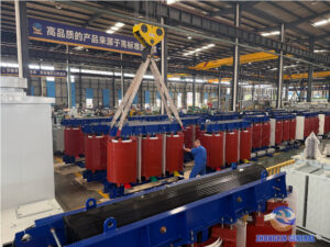
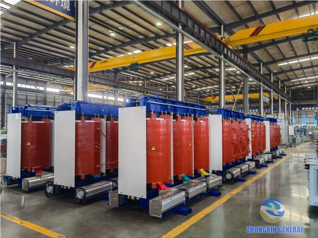
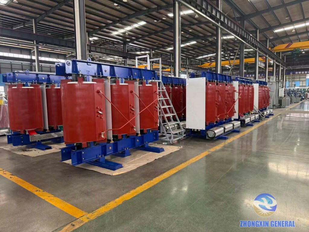
At the time, the first prototype was still going together on the assembly floor. A lot has happened since. Right now the last few units of this first batch are in final installation, assembly and testing. In days, all 20 dry-type transformers will roll off the line — complete, tested and ready to ship.
A Custom, Non-Standard Design Built for Energy Storage
This wasn’t something we could pull from standard inventory. A 5250 kVA rating isn’t on the national standard capacity list. So the winding molds and core dimensions were designed in-house for this order. The engineering team built the tooling, ran the first prototype, adjusted a few things, and then put it into production. That’s the advantage of design and manufacturing under one roof. When something needs tweaking, you don’t wait on an outside mold shop.
On the Production Floor: Copper Foil Winding and Vacuum Drying
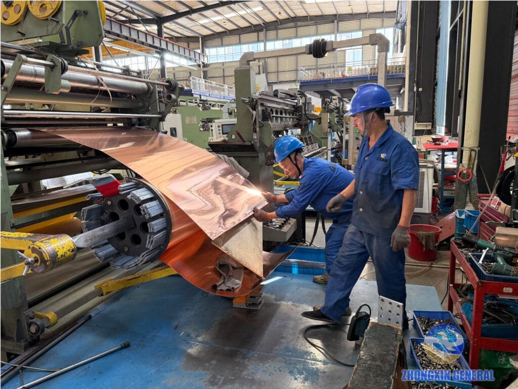
Every winding starts on the foil winding machine. The low-voltage winding is wound from wide copper foil, layer by layer, with interlayer insulation in between. Two technicians work the machine together. One feeds and guides the foil under tension. The other trims and deburrs the edges with a grinding tool, making sure every layer lies flat. A burr or misaligned layer here becomes a hot spot or partial-discharge problem later. So the foil edge gets careful attention before the winding leaves the mandrel.
Once wound, the coil goes into the casting mold for epoxy pouring, then into the vacuum drying chamber. The vacuum cycle pulls out residual moisture and trapped air. Moisture inside a cast-resin winding only shows up when the transformer fails years later. So the drying parameters are controlled strictly, and every cycle is logged.
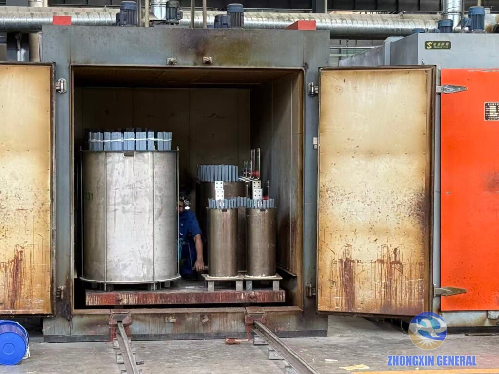
Air-Duct Removal, Core Stacking and Final Assembly
Out of the drying chamber, the casting is cured and the mold comes off. That’s when the air-duct strips get pulled out. These strips were placed between winding layers before casting. Once the resin is fully cured, a technician works each one loose and draws it out by hand. What’s left behind are the vertical cooling ducts that run the full height of the winding. It’s slow, deliberate work. Rush it and you’ll chip the cast surface. But this step is what turns a solid resin block into a winding that can dissipate heat under load.
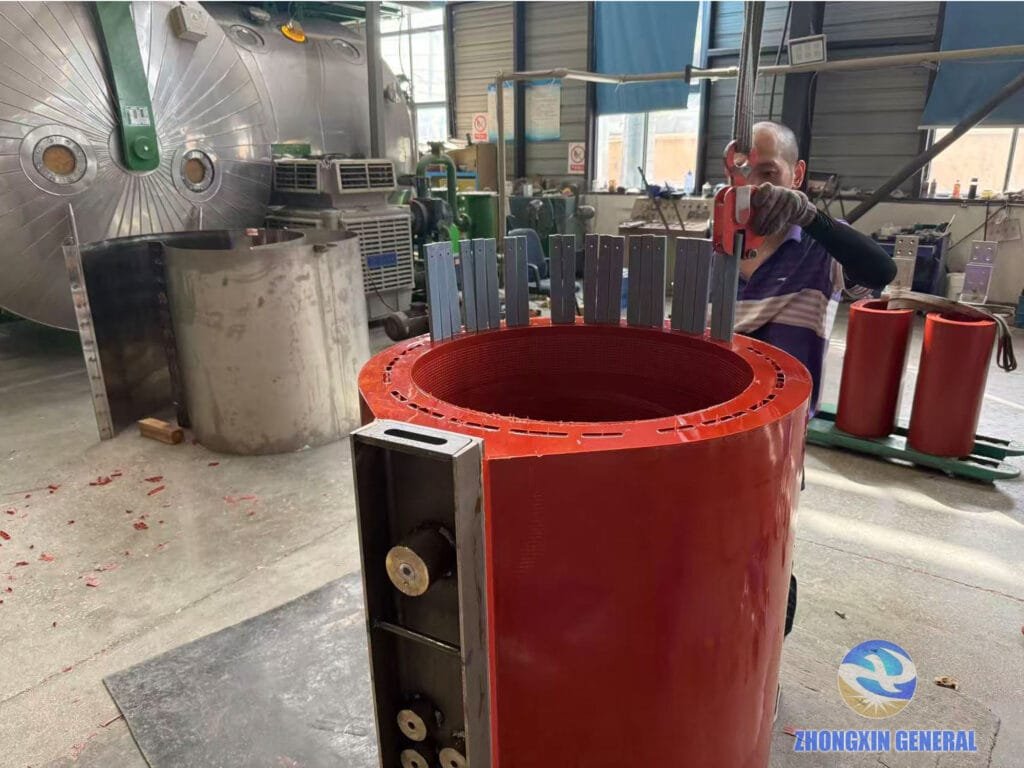
From there the winding gets a rest period. The cast surface is ground smooth. Then the core is stacked by hand, sheet by sheet. The stacking tension matters because it shows up later in two places. One is the no-load loss number on the test report. The other is the noise level once the transformer is actually running in the station.
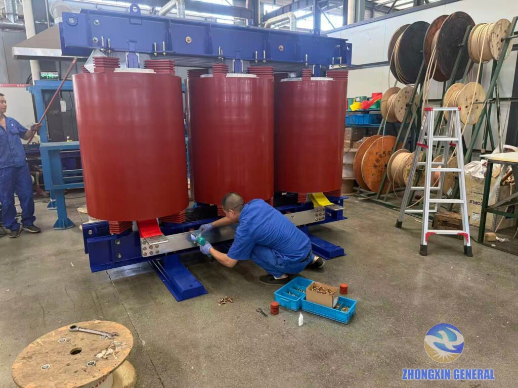
Over on the assembly floor, a technician works every busbar connection with a torque wrench. Parts lie in blue trays on the concrete beside him. A slightly loose connection here becomes a hot spot years later. So every bolt gets checked. These are the last few units of the first batch going through this final assembly step.
Factory Testing: Every Unit Must Pass Before It Ships
The last few units are now on the test floor. Now the countdown to all 20 transformers going off the line has begun. It’s the part nobody skips.
Every unit goes through the full routine. It starts with winding resistance on all taps, voltage ratio and phase check. Then insulation resistance, and no-load and load loss measurements. Finally applied voltage withstand, and induced voltage withstand with partial discharge. The test technician connects heavy red leads from the control cabinet to the high-voltage bushings. Nearby sits the test transformer, a few meters away. Then they run the numbers.
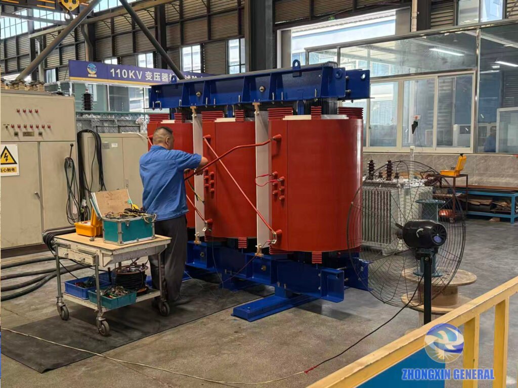
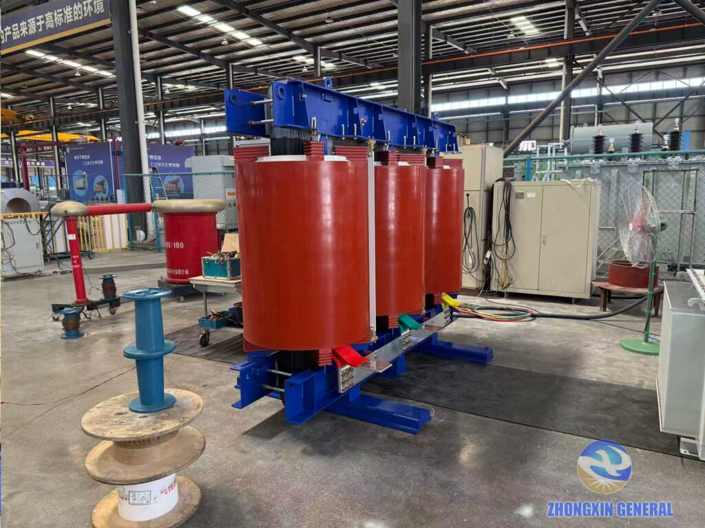
A banner on the wall in the test hall reads “Good products come from a high-standard environment.” If a number falls outside the acceptable range, that unit doesn’t get a pass. It goes back to the production floor, and the team finds out why. Each test report is reviewed and signed off before the unit moves to shipping.
Quality is the life of the company, as we say. In practice that means a failed test stops the shipment, regardless of the production schedule.
Engineering Details: Core Laminations and Clamp Finish
A couple of close-ups show a finish that doesn’t appear on a spec sheet. It shows up in years of reliable service.
Seen end-on, the core is hundreds of silicon steel laminations stacked tight. Each sheet is coated to suppress eddy currents, and then the whole surface is hand-brushed with black insulating varnish. Brush strokes are still visible in the finish, laid on evenly and worked into every gap between laminations. The varnish does three jobs. It locks the laminations together so the core doesn’t hum under load. It seals the surface against moisture and corrosion. And it cuts stray-flux losses that would otherwise heat the core from outside in. The gloss is uniform, with no runs and no bare spots. Customers never ask about it on the datasheet. But they notice it the first time they open the cabin door.
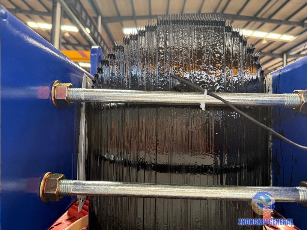
Right above it sits the top clamp assembly. It’s blue painted steel, with galvanized through-studs tensioned at both ends. Red post insulators carry the winding terminals. The clamp is machined and fitted in our own workshop. That blue paint goes on over a properly prepared surface, so it doesn’t chip when the studs are tensioned. Between the black-varnished core, blue clamp and red cast-resin windings, the finished transformer has a clean, deliberate look.
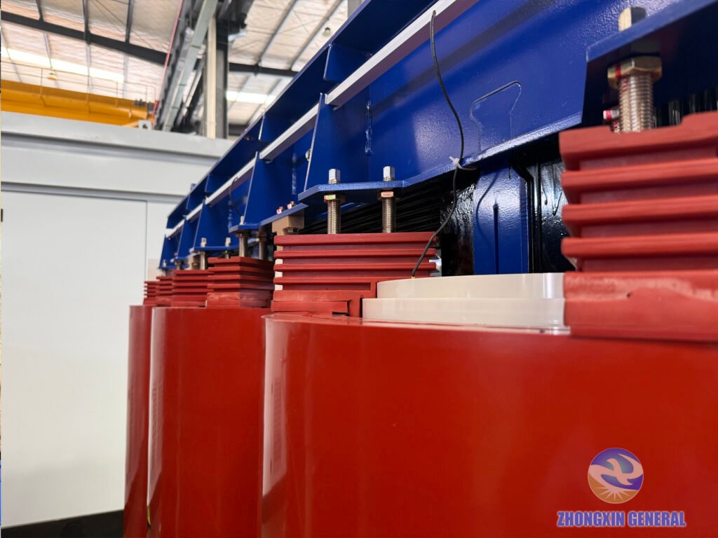
Even the cooling ducts between winding layers were sized with energy storage specifically in mind. The PCS converters in these stations generate harmonic currents that add extra heat to the windings. A standard distribution transformer doesn’t see that kind of loading pattern day after day.
A Complete Package: Transformer, Switchgear and Prefabricated Cabin
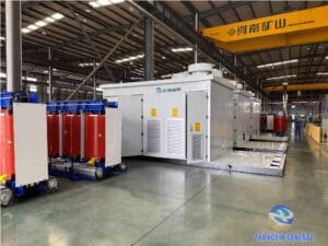
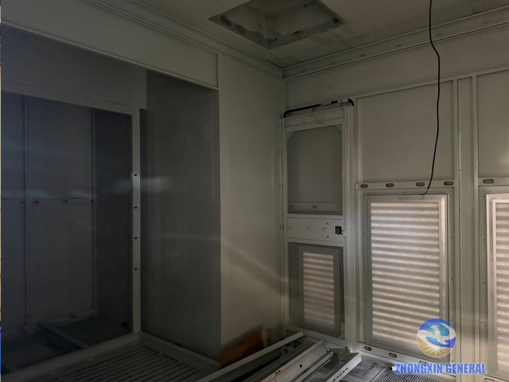
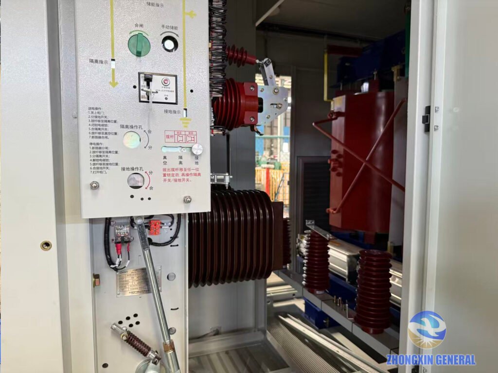
These transformers aren’t shipping alone. The same energy storage station needs medium-voltage switchgear. That means vacuum circuit breakers, disconnectors and earthing switches. All housed inside a prefabricated cabin alongside the transformer. We’ve been building the switchgear in parallel. So when the transformer unit is installed into its bay, everything connects on site without surprises.
Why Energy Storage Needs a Purpose-Built Transformer
Energy storage is where a lot of the renewable energy transition actually lands. Solar and wind generate when conditions are right. Batteries store it and push it back out when the grid needs it. The transformer in the middle sees power going both ways. It sees harmonic content from the converters. And constant thermal cycling as the station charges and discharges. It’s a harder job than a standard distribution transformer. The design has to account for all of it from the start.
That’s the work we’re set up to do — build reliable power equipment for the low-carbon energy transition.
All units are approaching completion of manufacturing
These are the last units of the first batch. Once their final tests are reviewed and signed off, all 20 dry-type transformers will be complete. Then each unit will be installed into its prefabricated cabin bay alongside the MV switchgear. The complete integrated package will then be prepared for shipment. Production of the remaining 20 units will follow based on project progress and customer feedback.
If you are working on an energy‑storage project requiring non‑standard dry‑type transformers, or you have other transformer‑related requirements, please feel free to contact us. Our engineering team can deliver professional technical support.That means custom capacities, specific voltage ratios, or other specialized requirements.
For more information, visit our case studies page, or browse recent updates in our Company News section.