Full Case Study for Dedicated Industrial Zone Power Supply
Project Snapshot
| Item | Details |
| Product | 16,000 kVA On-Load Tap-Changing (OLTC) Oil-Immersed Power Transformer |
| Voltage Ratio | 35kV / 10.5kV |
| Application | Main transformer for dedicated industrial zone substation — steps dedicated 35kV line supply down to 10.5kV for zone-wide distribution |
| Final Step-down | Terminal distribution transformers will further step 10.5kV down to 0.4kV for individual factory connections |
| Tap Changer Type | On-load (OLTC) — continuous voltage regulation under full load without supply interruption |
| Cooling Mode | ONAN / ONAF |
| Dispatch Date | April 11, 2026 |
| Manufacturing Period | Core stacking → Winding → Assembly → Testing → Dispatch (full cycle documented below) |
| Project Status | Dispatched — awaiting site installation and commissioning |
Background: Powering an Entire Industrial Zone
Industrial zones present a unique power supply challenge. Unlike a single factory with predictable load patterns, an entire zone must accommodate multiple tenants — each with different equipment, varying demand profiles, and independent start-up schedules. The main incoming substation transformer must therefore handle not only high total capacity (16,000 kVA in this case) but also significant voltage fluctuations as tenants come online and offline throughout the day.
This transformer was commissioned by a dedicated industrial zone operator to serve as the primary step-down transformer for their entire facility. The zone receives a dedicated 35kV supply line from the regional grid. This transformer steps that voltage down to 10.5kV, which is then distributed across the zone to multiple terminal distribution transformers, each further stepping down to 0.4kV for individual factory connections.
The critical requirement for this application is voltage stability under varying load conditions. With multiple tenants connecting and disconnecting, the primary transformer must maintain a stable 10.5kV output regardless of fluctuations on the 35kV incoming supply or changes in zone-wide load.
This is why the client specified an on-load tap-changing (OLTC) transformer — enabling continuous voltage regulation without ever interrupting power to the zone.
Complete Production Documentation
The following images document the complete manufacturing process of this 16,000 kVA OLTC transformer — from the first silicon steel lamination to the final dispatch convoy.
1. Core Stacking — The Foundation of Efficiency
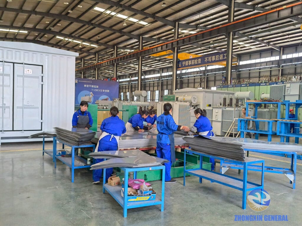
The core is the heart of any transformer’s energy efficiency. For this 16,000 kVA unit, high-permeability grain-oriented silicon steel was used, stacked in a step-lap configuration to reduce no-load losses and magnetising current. The quality of core stacking directly determines the transformer’s efficiency over its 30+ year service life.
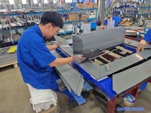
2. Winding Assembly and Drying
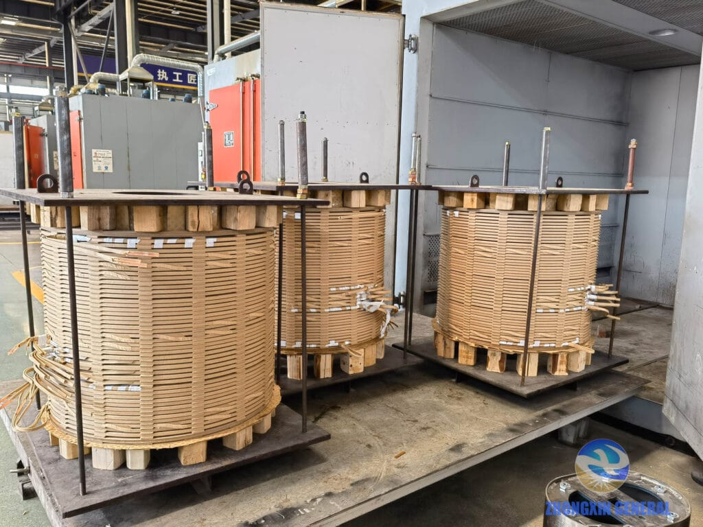
The winding assemblies are manufactured from high-purity electrolytic copper. Before oil-filling, the entire winding assembly undergoes drying to remove residual moisture from the cellulose insulation system. Any remaining moisture would compromise dielectric strength and accelerate insulation aging over time.
3. Tap Lead Connections — The OLTC Interface
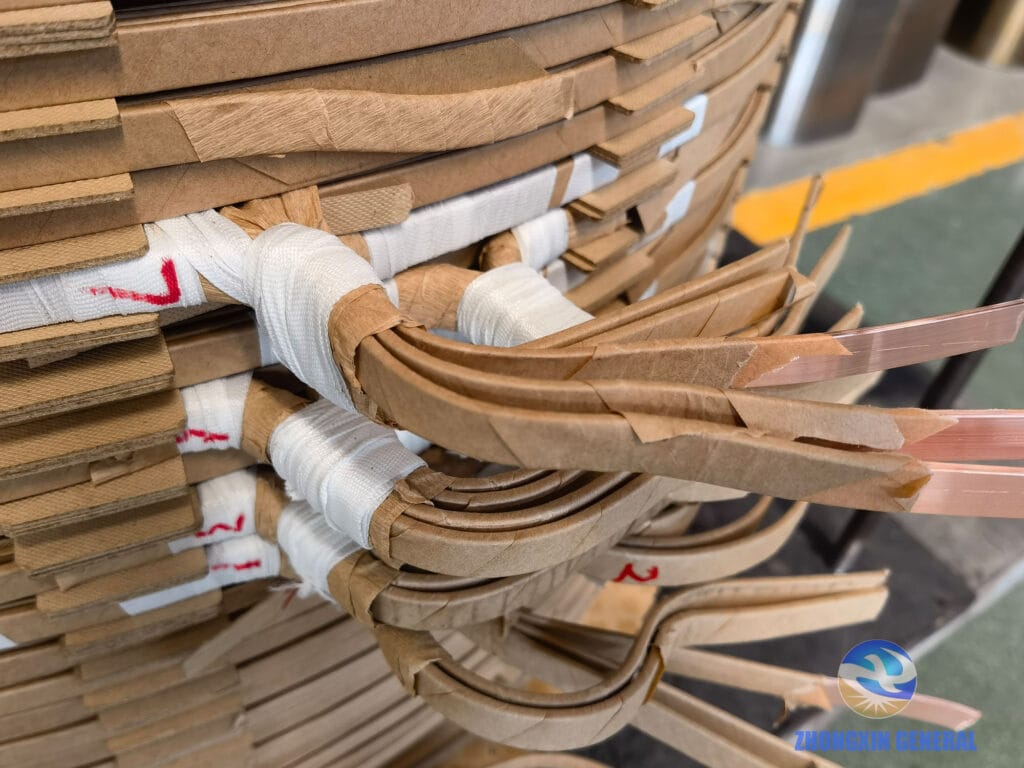
These leads connect the winding to the on-load tap changer mechanism. The OLTC allows the transformer to adjust its voltage ratio under full load — selecting different tap positions on the 35kV winding to maintain stable 10.5kV output regardless of grid voltage variation.
4. Winding-to-Core Mechanical Fixing
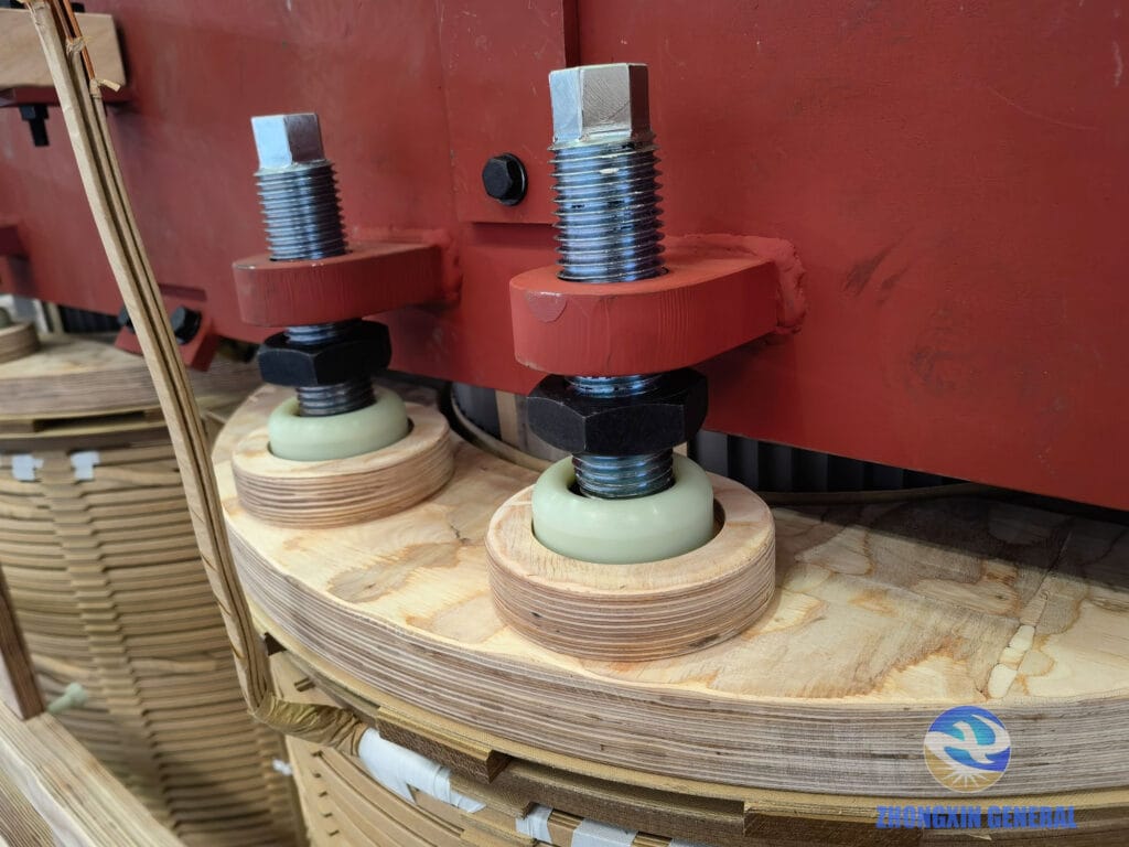
Precise mechanical fixturing at this stage determines the transformer’s ability to withstand short-circuit forces and resist vibration throughout its service life. The clamping pressure must be sufficient to prevent winding movement under fault conditions but not so high as to damage insulation.
5. Complete Active Part — Before Lead Installation
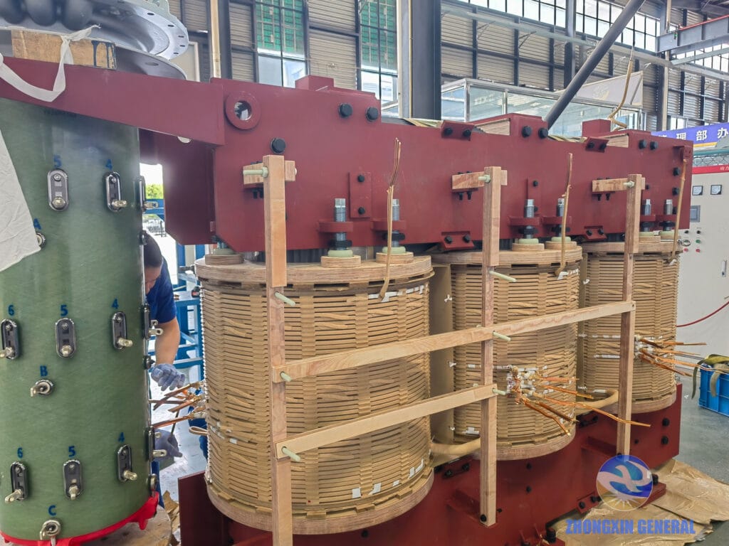
This is the structural and electrical heart of the transformer — core and windings fully assembled, photographed before lead installation begins. From this point, the active part will be lowered into the tank, leads will be connected to the bushings, and the unit will be prepared for oil-filling.
6. Tank Fabrication — Base Detail
The tank base must support the full weight of the active part (approximately 8-10 tonnes for this capacity) plus approximately 8,000-10,000 litres of insulating oil. The base is also engineered to distribute load evenly for both permanent foundation mounting and heavy transport configurations.
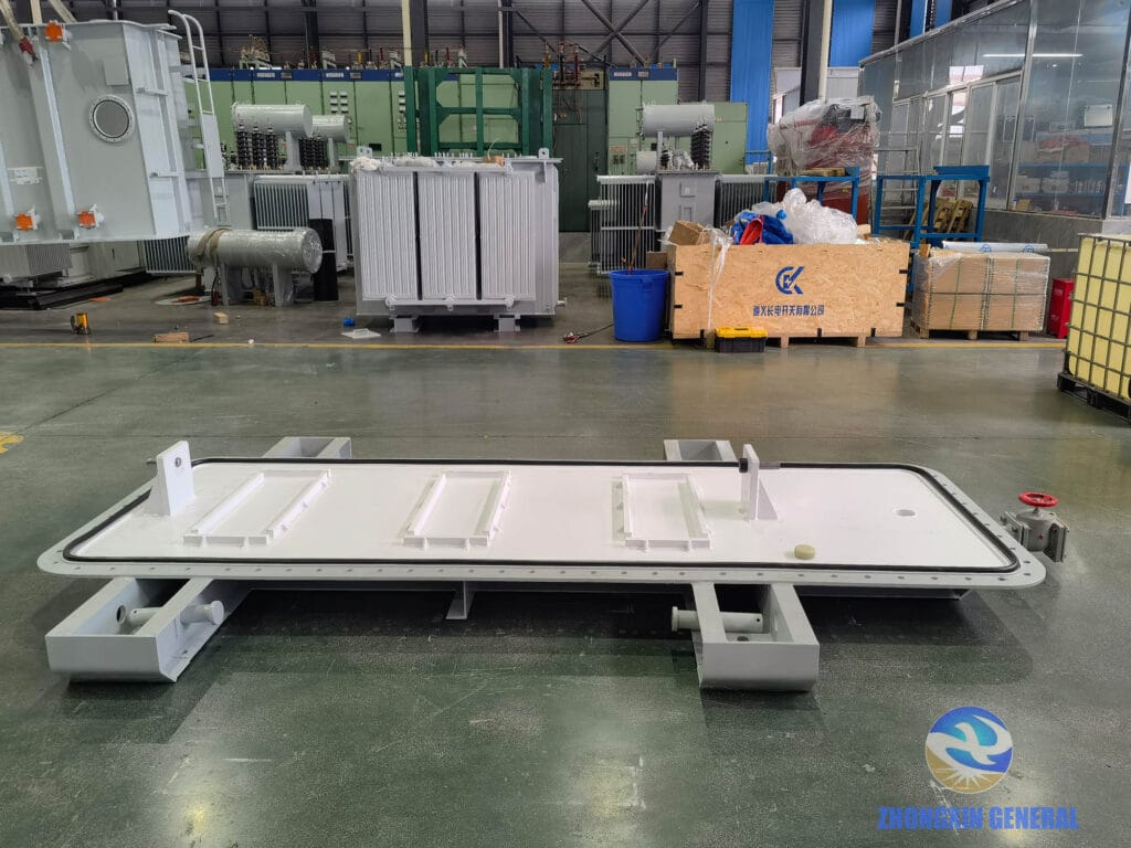
7. Tank Fabrication — Upper Section
The upper tank section showing the main cover plate, fitting penetrations for bushings and instrumentation, and sealing surfaces. Tank integrity at this level is critical for long-term oil containment and moisture exclusion.
8. Oil Drain Valve Detail
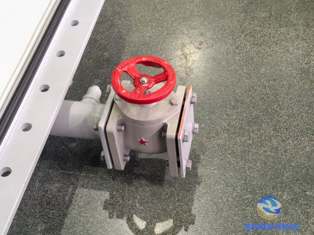
The oil drain valve is a routine maintenance access point throughout the transformer’s service life — used for insulating oil sampling, oil replacement, and transport preparation. For this project, the valve will be accessed during site commissioning for oil testing before the unit is energised.
9. Conservator Tank Installation
The conservator (oil expansion tank) maintains constant oil pressure in the main tank and accommodates thermal volume changes as the transformer heats up and cools down during load cycles. The breather system, fitted with a silica gel air dryer, prevents atmospheric moisture from entering the oil circuit.
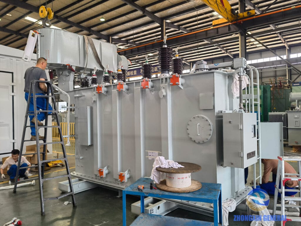
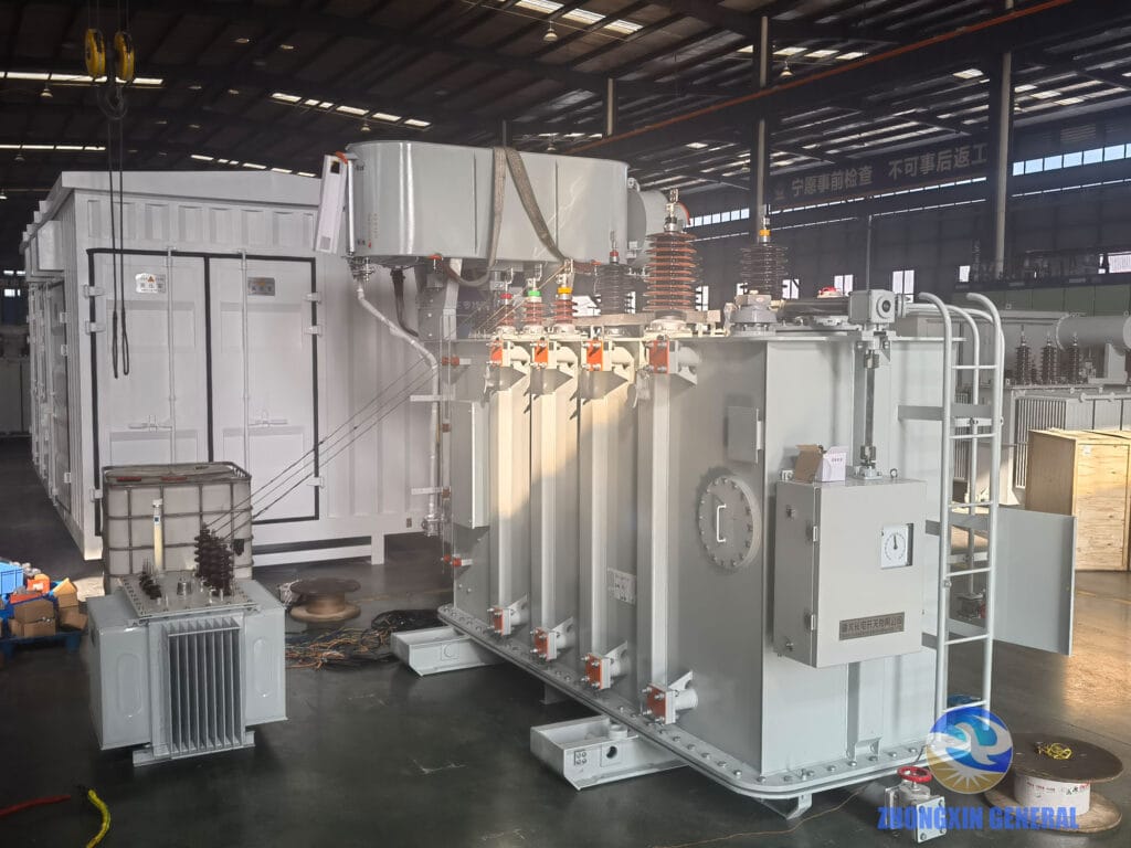
10. Conservator and Bushings — Fully Installed
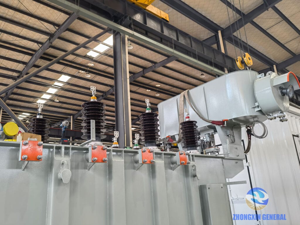
With the conservator tank and HV/LV bushings fully installed, the transformer’s external configuration is complete. The high-voltage bushings (35kV side) are noticeably larger and taller than the low-voltage bushings (10.5kV side) — a visual indicator of the voltage step-down function.
11. OLTC Control Cabinet — Side View
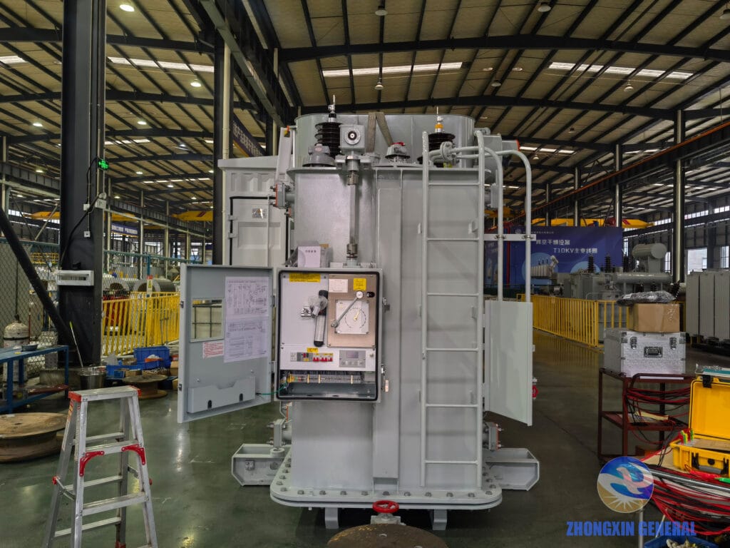
The OLTC control cabinet houses the motor drive mechanism that selects tap positions. The control cabinet can be operated locally (via manual controls) or remotely (via SCADA interface), allowing the zone operator to adjust voltage without dispatching personnel to the substation.
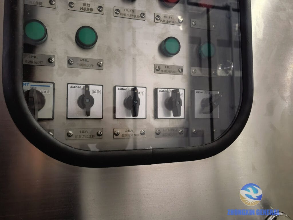
12. Fan Cooling Control Cabinet
13. Factory Acceptance Test Preparation
Before any transformer leaves the factory, it must pass a comprehensive test programme. This unit underwent:
| Test | Purpose |
|---|---|
| Winding resistance measurement | Verify connection integrity and detect manufacturing defects |
| Voltage ratio and phase displacement | Confirm correct tap changer operation at all positions |
| No-load loss and current | Measure core performance and magnetising characteristics |
| Load loss and short-circuit impedance | Verify copper loss and impedance at rated current |
| Dielectric tests (induced overvoltage / separate source) | Confirm insulation integrity at above-operating voltages |
| OLTC sequence and timing test | Verify correct tap changer operation across full range |
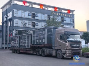
14. Dispatch — Loaded and Secured (View from Factory Gate)
On April 11, 2026, the completed transformer — main body, cooling fans, and radiator panels — was loaded onto a heavy transport vehicle. This view is taken from the factory gate, looking back toward the workshop. The dimensions of a 16,000 kVA transformer require careful load distribution and multiple securing points to meet road transport regulations.
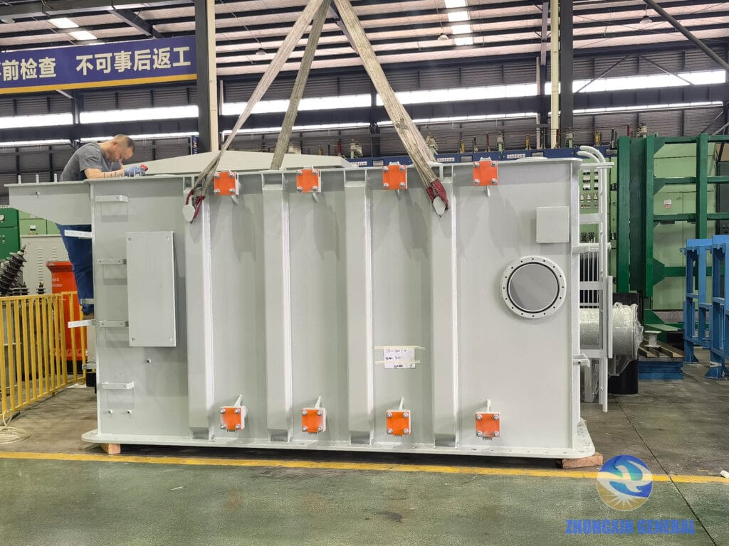
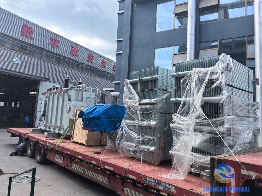
15. Dispatch — Loaded and Secured (View from Workshop)

This second view, taken from inside the workshop looking toward the factory gate, shows the full transport configuration. The radiator panels are mounted on both sides of the main tank, and the cooling fans are secured in position. The unit is now ready for the road journey to the industrial zone site.
Project Significance: Reliable Power for Industrial Growth
This 16,000 kVA OLTC transformer is not just a piece of equipment — it is the electrical backbone of an entire industrial zone. Every factory within the zone, from heavy manufacturing to light assembly, depends on this single unit to deliver stable, reliable power at the correct voltage.
The on-load tap-changing capability is particularly critical for this application. Industrial zones experience wide load swings throughout the day — morning start-ups, mid-day peak loads, evening shut-downs — and the 35kV incoming supply can also vary. The OLTC automatically adjusts the tap position to maintain a stable 10.5kV output regardless of these fluctuations, ensuring that every connected factory receives power within acceptable voltage tolerances.
Once this transformer is commissioned on site, the zone’s complete power chain will be:
35kV Grid Supply
↓
[THIS TRANSFORMER] — 35kV → 10.5kV (OLTC regulated)
↓
the whole industril zone-wide 10.5kV Distribution Network
↓
Terminal Distribution Transformers — 10.5kV → 0.4kV
↓
Individual Factory Connections
International Standards Compatibility
Zhongxin General designs and manufactures power transformers to multiple international standards:
| Standard | Target Markets |
|---|---|
| GB / Chinese Standard | Domestic China, Belt and Road markets |
| IEC 60076 | Europe, Southeast Asia, Middle East, Africa |
| ANSI / IEEE C57 | Americas |
Special environmental specifications (high altitude, tropical humidity, seismic zones, extreme cold) are available on request.
→ Xinjin People’s Hospital Power Distribution System (dry type transformers and switchgears)
→ 8,000 kVA OLTC Transformer Export to DR Congo — International logistics and nitrogen transport
→ 31,500 kVA OLTC Transformer — Jingten Energy 35kV Substation
→ 63 MVA/110 kV OLTC Transformer — Ningxia LNG & Helium Project
About Zhongxin General Electric Energy Co., Ltd.
Zhongxin General is a Sichuan-based National “Little Giant” Enterprise and National High-Tech Enterprise manufacturing oil-immersed and dry-type power transformers (30 kVA to 100 MVA, 0.4 kV to 138 kV), medium-voltage switchgear, prefabricated substations, microgrids, and energy storage systems. The company is a strategic partner of State Grid Corporation of China and China Southern Power Grid.
Enquire About Your Project
Whether you need an OLTC transformer for an industrial zone, a standard distribution transformer for a commercial facility, or a complete prefabricated substation for a remote site — Zhongxin General’s engineering team can design a solution for your specific requirements.
→ Contact Our Engineering Team
→ View Power Transformer Product Range
→ Browse All Case Studies