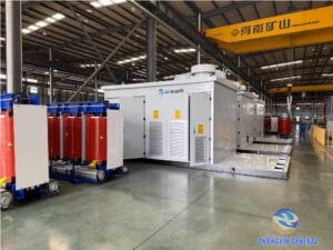
Against the backdrop of global dual-carbon goals, photovoltaic (PV), wind power, and energy storage projects are being deployed on a large scale worldwide. As the core equipment for voltage conversion, power collection, and grid connection of new energy power stations, transformers directly determine the 25-year full-life-cycle safety, power generation efficiency, and investment return of the entire station.
Different from traditional thermal power systems, new energy power generation features intermittency, volatility, high harmonic content, and frequent load impact. It is infeasible to apply the selection logic of traditional power distribution transformers to PV, wind, and energy storage projects. This article comprehensively sorts out practical transformer selection key points for new energy stations from multiple dimensions, including working condition scenarios, equipment types, core electrical parameters, energy efficiency compliance, common selection pitfalls, and intelligent operation and maintenance, providing authoritative references for engineering design, equipment procurement, and bidding evaluation.
1. Core Differences Between New Energy Transformers and Traditional Transformers
Traditional thermal power transformers operate with stable output and minor load fluctuations. In contrast, PV, wind power, and energy storage stations have special operating conditions that impose higher performance requirements on transformers, mainly reflected in four aspects:
1.1 Load Characteristic Differences
PV systems generate power during the day and remain unloaded at night; wind power output fluctuates drastically with wind speed changes; energy storage systems operate in bidirectional charge-discharge modes with frequent load jumps. New energy transformers long-term operate in alternating light and heavy load states, making no-load loss a critical factor affecting overall station revenue.
1.2 Power Quality Differences
Inverters and PCS (Power Conversion Systems) in new energy systems generate massive harmonics, causing additional winding heating. New energy transformers must be equipped with strong harmonic resistance to ensure stable operation.
1.3 Environmental Working Condition Differences
Most PV, wind, and energy storage stations are built in deserts, mountainous areas, coastal salt-fog zones, high-altitude and extreme cold regions. Transformers need to adapt to harsh outdoor environments with high weather resistance and corrosion resistance.
1.4 Expanded Grid Connection Functions
New energy transformers need to support exclusive functions such as electrical isolation, PID suppression, low-voltage ride-through, and fault current limiting. For some scenarios, split winding design is required to isolate multiple inverter outputs and suppress branch circulation.
Specifically, PV transformers can realize electrical isolation, block DC component and leakage current from entering the grid, boost the negative potential of modules to suppress PID attenuation, and match grid voltage standards of different countries.
2. Transformer Selection by Working Conditions: Dry-Type vs Oil-Immersed, Box Substation Classification
According to different heat dissipation media, installation environments and functional requirements, new energy transformers are divided into dry-type transformers, oil-immersed transformers, and box-type substations (box transformers), with distinct applicable scenarios and performance advantages.
2.1 Dry-Type Transformers (SCB/SCBH Series)
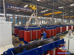
Dry-type transformers adopt air cooling and epoxy resin pouring insulation, featuring oil-free, fireproof and explosion-proof performance with no oil leakage or fire hazards.Applicable scenarios: Industrial and commercial rooftop distributed PV, factory indoor power distribution, energy storage cabins and indoor energy storage stations, and internal equipment of offshore wind turbine nacelles.
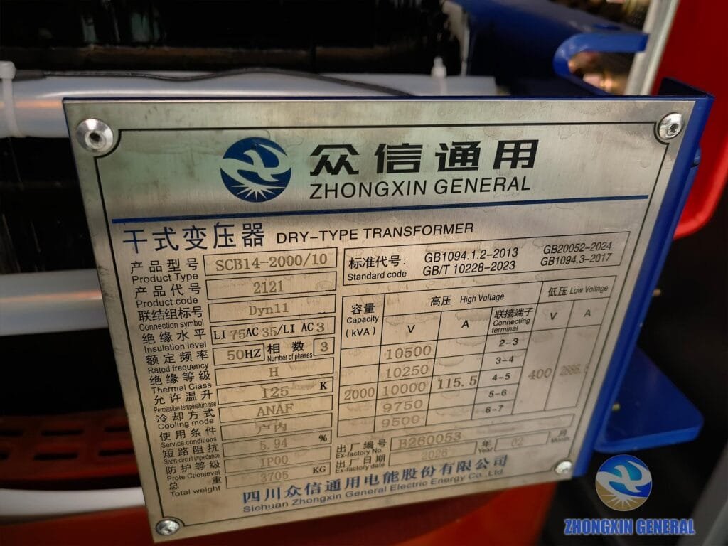
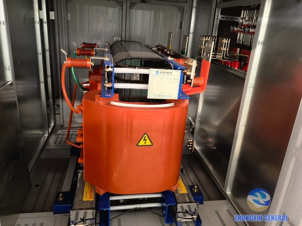
Advantages: Fire and explosion proof, zero oil leakage risk, simple maintenance, and can be arranged at load centers to reduce line loss. Disadvantages: Higher procurement cost, large volume for large-capacity models, and high dust-proof pressure in sandy environments.
2.2 Oil-Immersed Transformers (S/SFZ Series, S20/S22 Mainstream Models)
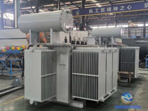
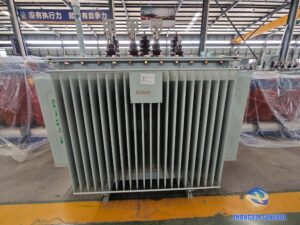
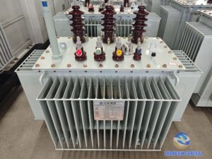
Oil-immersed transformers use transformer oil for cooling and insulation, with excellent heat dissipation, high overload margin, and prominent cost advantages for large-capacity applications. Applicable scenarios: Large-scale centralized ground PV stations, mountain and desert PV projects, onshore wind turbine tower bottom box transformers, and main transformers of boost stations.
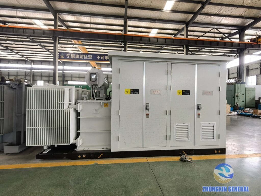
Advantages: Outstanding heat dissipation performance, strong overload resistance, and low unit cost for large-scale outdoor stations. Disadvantages: Potential oil leakage and fire risks, requiring regular inspection of oil level and quality, and supporting fire prevention and anti-leakage design.
2.3 Box-Type Substation Selection: American vs European Type
Box-type substations are complete sets of equipment widely used in PV and wind farms, integrating transformers, high and low voltage switches, metering, and reactive power compensation devices, divided into American and European types:
- American Box Transformer: Load switches and fuses are immersed in the transformer oil tank, featuring compact structure, small size and low cost, suitable for flat terrain centralized PV stations; disadvantage is narrow maintenance space.
- European Box Transformer: Independent partition design for high-voltage room, transformer room and low-voltage room, convenient maintenance and good heat dissipation, suitable for high-altitude, extreme cold and sandy mountain projects; disadvantages are larger overall volume and higher equipment cost.
2.4 Double-Winding vs Double-Split Transformer (Key for PV Boosting)
- Double-Winding Transformer: Equipped with one set of high-voltage and one set of low-voltage windings, simple structure and low cost. Suitable for multi-inverter parallel scenarios with LCL filter schemes, suppressing circulation through inverter filtering to control project costs.
- Double-Split Transformer: One high-voltage winding and two electrically independent low-voltage windings, separately connected to two inverters to realize electrical isolation, suppress parallel circulation, reduce harmonics and improve power quality. Priority for dual-inverter parallel scenarios with LC filter schemes, with a 15%-20% higher procurement cost than ordinary double-winding transformers.
3. Scenario-Based Selection Strategy: PV | Wind Power | Energy Storage
3.1 PV Power Station Transformer Selection
3.1.1 Distributed PV (Industrial and Commercial Rooftop)
- Capacity Matching: Below 8kW accesses 220V voltage; 8kW-400kW accesses 380V low voltage; above 400kW accesses 10kV medium voltage grid; above 5MW can adopt 35kV grid connection.
- Equipment Type: Priority to SCB14/SCB18 series high-efficiency dry-type transformers
- Capacity Ratio Standard: When using existing public grid transformers, the total PV installed capacity shall not exceed 25% of the maximum load of the superior transformer to avoid reverse power flow impact; for dedicated PV boost transformers, the capacity ratio of modules to transformers is 1:1 or the transformer capacity is slightly larger, with 10%-25% margin reserved to ensure no overload at peak output, maintaining the economic load rate at 60%-75%.
- Wiring Group: Priority to Dyn11/Dy11 to suppress triple harmonics
- Voltage Ratio: Low voltage matches inverter output 690V/800V, high voltage adopts 10kV/35kV
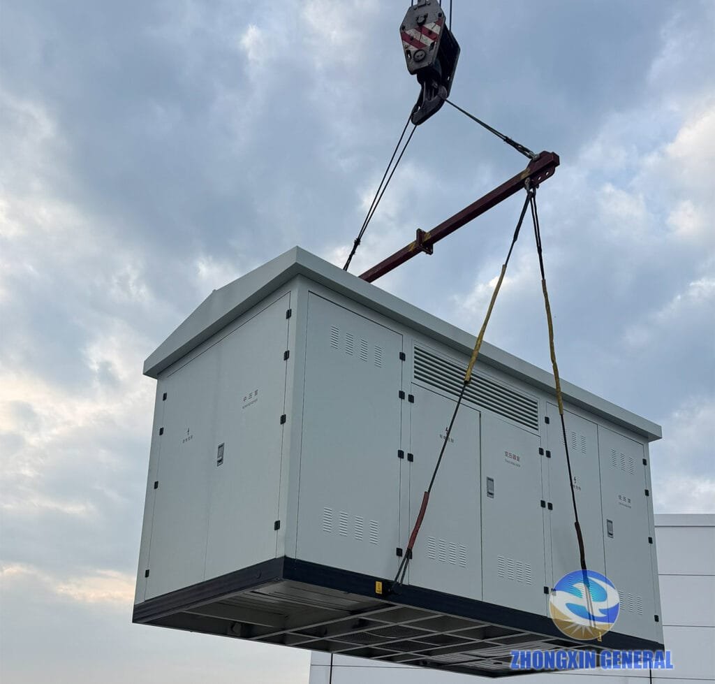
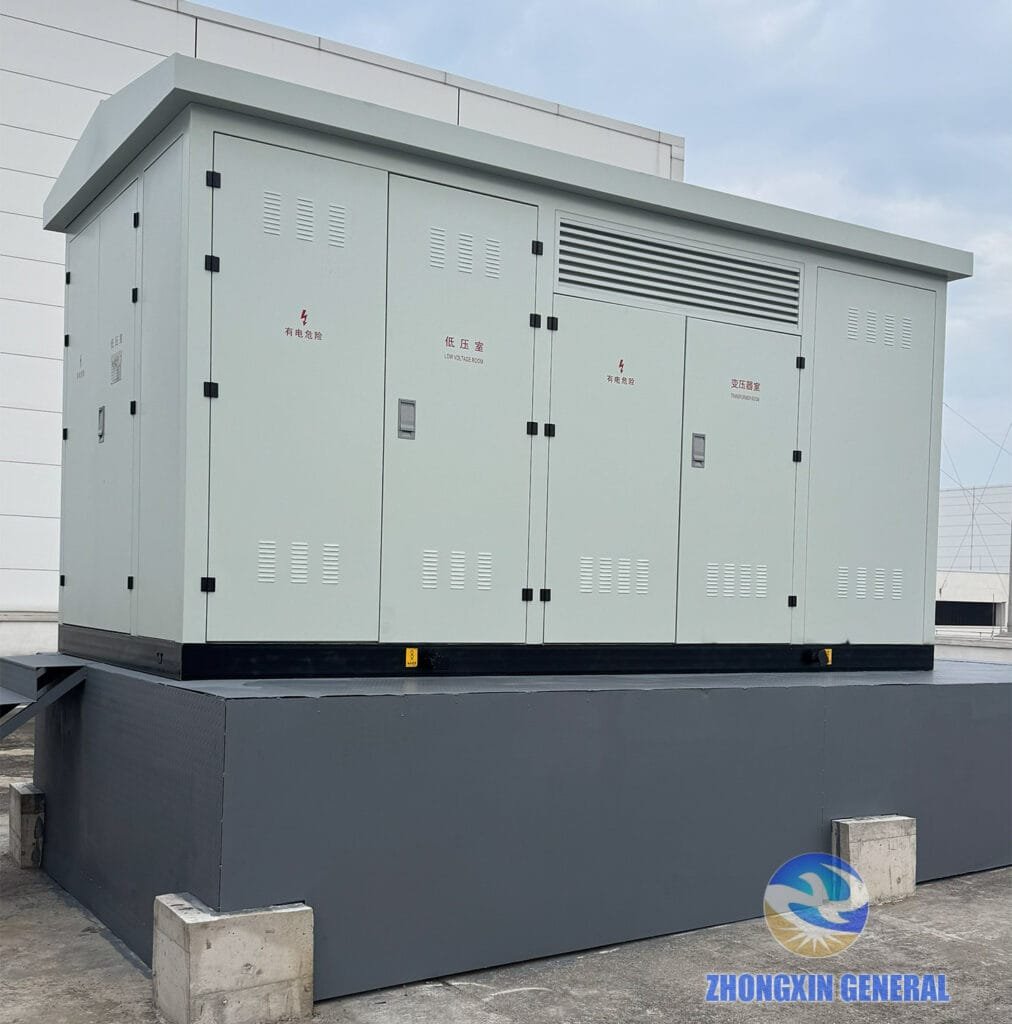
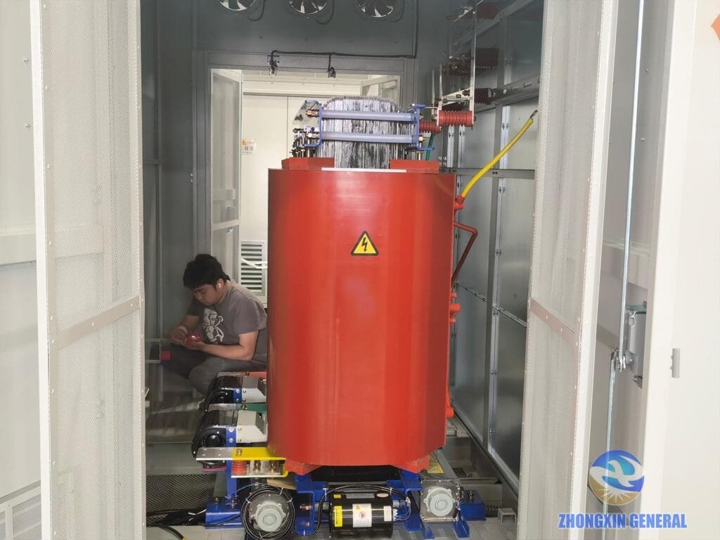
We have rich practical experience in distributed PV transformer supporting projects. The Sichuan Tobacco Shifang Distributed PV Project adopts self-developed SCB14 high-efficiency dry-type transformers and supporting box-type substations, realizing stable grid connection and efficient power generation of industrial rooftop PV systems.
3.1.2 Centralized Ground PV (Mountain, Desert, Agri-PV Complementary)
- Equipment Selection: Priority to oil-immersed box transformers; desert and sandy areas require protection grade ≥IP54; coastal tidal flat projects adopt C5 anti-corrosion grade
- Field Box Transformer Capacity: Mainstream single-unit capacity 2500-3150kVA
- Boost Station Main Transformer: Large-capacity projects adopt on-load tap-changing oil-immersed main transformers, with single large-capacity or multi-unit parallel configuration according to total installed capacity
3.2 Wind Farm Transformer Selection
- Onshore Wind Turbine Tower Bottom Box Transformer: Adopt oil-immersed box transformers with anti-vibration and low-temperature resistance; electric heating devices are equipped for extreme cold regions
- Offshore Wind Turbine Nacelle Transformer: Must adopt high-grade salt-fog corrosion resistant dry-type transformers
- Wind Farm Boost Station Main Transformer: Adopt YNd11 wiring group on-load tap-changing oil-immersed transformers; considering severe wind power fluctuation, the capacity margin is recommended to be 10%-15%. Classic configurations include 2×50MVA or 1×100MVA for 100MW projects, and 2×100MVA for 200MW projects, with short-circuit impedance controlled at 10.5%-14%.
3.3 Energy Storage Power Station Transformer Selection
Energy storage systems feature bidirectional PCS charge-discharge, high harmonic content and frequent load impact, which are the key and difficult points of transformer selection:
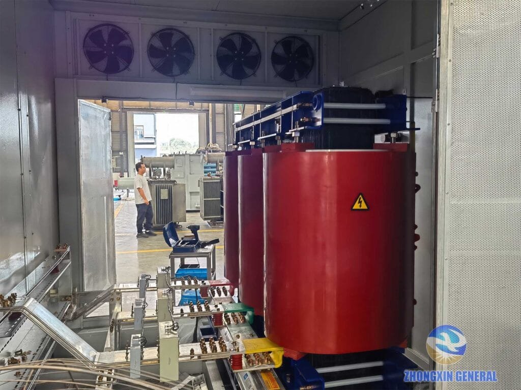
- Equipment Type: Dry-type transformers are preferred for electrochemical energy storage cabins to prioritize fire safety; oil-immersed transformers can be used for large independent energy storage boost stations
- Capacity Calculation: Transformer capacity = PCS rated power × 1.2-1.3 margin, covering bidirectional peak power of charging and discharging instead of unidirectional power
- Core Requirements: Support bidirectional power transmission, harmonic resistance, short-circuit impedance 6%-10% to limit fault short-circuit current; outdoor integrated box transformer protection grade ≥IP54, cabin internal transformer protection grade IP20-IP30
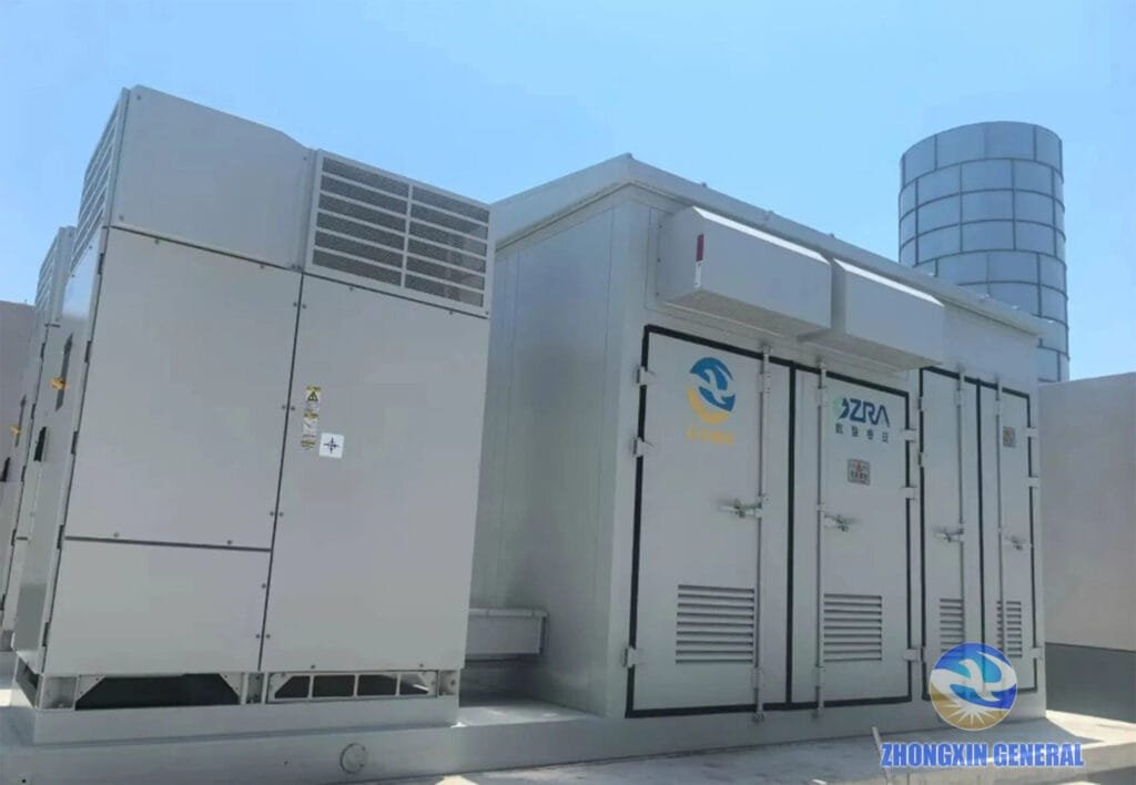
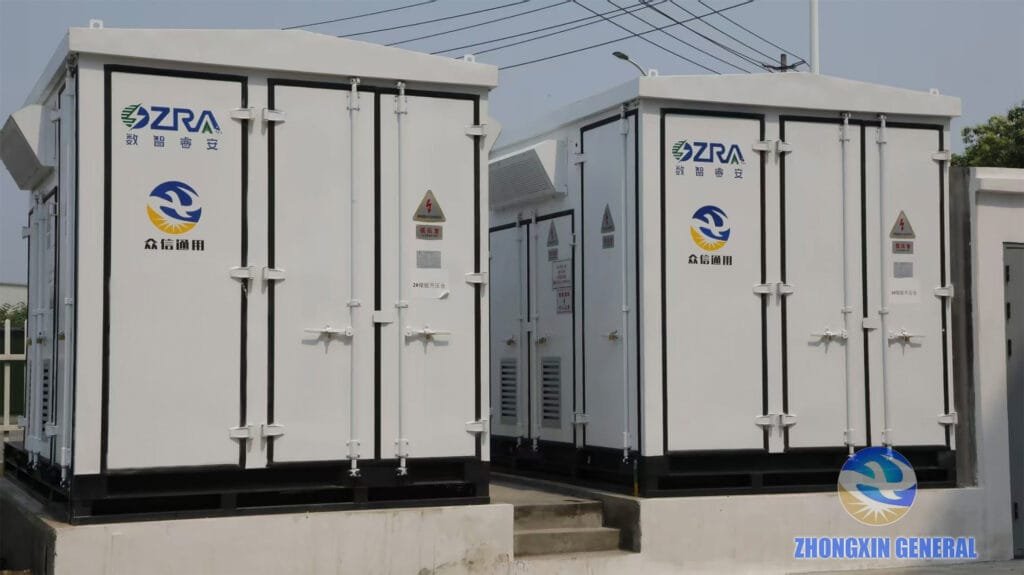
Our company has completed multiple benchmark user-side energy storage transformer supporting projects. Neijiang Weiyuan 5.175MW/10.03MWh energy storage project and Chengdu Xinjin Fangxin 10MW/h energy storage project adopt customized energy storage special boost transformers, realizing stable bidirectional operation and significant power saving benefits.
4. Core Electrical Parameter Selection Key Points
4.1 Rated Capacity: Avoid Overcapacity and Undercapacity
Too small capacity will cause overload at peak output, winding overheating, accelerated insulation aging and tripping failure; excessive capacity leads to long-term light-load operation, sharply increased no-load loss, huge full-life-cycle power loss, and failure to meet GB20052-2024 energy-saving standards.
Practical Capacity Margin Standard:
- PV station: Transformer capacity ≥ PV module installed capacity × 1.1-1.25
- Wind farm: Main transformer capacity ≥ Total wind turbine rated power × 1.1-1.15
- Energy storage station: Transformer capacity ≥ Total PCS rated power × 1.2-1.3
4.2 Voltage Ratio: Match Inverter/PCS Output and Grid Level
Domestic mainstream grid connection voltage specification:
- Low voltage side: PV inverter conventional output 690V/800V, energy storage PCS low voltage 0.69kV
- High voltage side: Distributed projects adopt 10kV; large-scale new energy stations adopt 35kV collection, then boost to 110kV/220kV for power transmission
4.3 Wiring Group Selection
- 10kV/35kV boost box transformer: Priority to Dyn11/Dy11. The triangular high-voltage winding locks triple harmonic circulation inside the winding, avoiding grid injection, and improves tolerance to three-phase unbalance and harmonics. The old Yyn0 type is not recommended for new projects.
- 110kV and above high-voltage boost main transformer: Adopt YNd11, with high-voltage star grounding to adapt to large grid grounding system.
4.4 Short-Circuit Impedance Uk (Critical for Avoiding Project Risks)
- 10kV box transformer: Short-circuit impedance 4%-6%
- 35kV box transformer: Recommended short-circuit impedance 7%-8%
Excessively low impedance leads to huge system short-circuit current, making switchgear difficult to break faults; excessively high impedance causes poor voltage regulation rate and severe voltage drift under load fluctuation, affecting normal inverter operation. The impedance parameter must be comprehensively determined combined with system short-circuit calculation results instead of copying sample parameters blindly.
4.5 Winding Material: Priority to All-Copper Winding
Aluminum winding transformers have low procurement cost but poor conductivity, larger winding cross-section, and easy oxidation and heating of joints, with high failure rate under frequent fluctuation working conditions of new energy. For PV, wind and energy storage projects with a 25-year operation cycle, all-copper winding transformers are prioritized. Although the initial cost is higher, they feature low full-life-cycle failure rate and better comprehensive economic benefits, and copper-clad aluminum products are prohibited for intelligent new energy transformers.
5. Energy Efficiency Compliance: Comply with GB20052-2024 Mandatory National Standard
GB20052-2024 Limited Values and Energy Efficiency Grades for Power Transformers was officially implemented on February 1, 2025, bringing new energy special transformers into mandatory supervision. The standard divides energy efficiency into three grades, with Grade 3 as the minimum access threshold, and old S11/SCB10 series are prohibited for new construction projects.
- Oil-immersed transformer: S22 (Grade 1 energy efficiency), S20 (Grade 2 energy efficiency), S18 (Grade 3 energy efficiency)
- Dry-type transformer: SCB18 (Grade 1 energy efficiency), SCB14 (Grade 2 energy efficiency)
- Amorphous alloy transformer: No-load loss is 60%-80% lower than ordinary silicon steel sheet transformers, which is very suitable for PV scenarios with long-term no-load operation and can effectively reduce iron loss.
Energy Efficiency Selection Avoidance: Do not judge energy efficiency only by model. It is necessary to require manufacturers to provide CMA third-party test reports to verify the measured values of no-load loss and 75℃ load loss and avoid false energy efficiency calibration. New energy transformer nameplates shall mark application codes (G for PV, F for wind power) and loss codes in accordance with JB/T3837-2025.
Loss focus differentiation: PV projects are dominated by no-load/light-load operation, focusing on no-load loss control; wind power and energy storage projects have severe load impact, requiring simultaneous control of load loss and no-load loss.
6. Extreme Environment Adaptation Selection Points
6.1 Coastal Salt-Fog Areas
Adopt hot-dip galvanizing + powder spraying for shell, 316L stainless steel fasteners, reach C4/C5 anti-corrosion grade, and pass more than 1000h salt spray test to resist coastal humid salt-fog erosion.
6.2 High-Altitude Areas (Above 1000m)
Thin air leads to decreased insulation strength. It is necessary to enlarge insulation gaps and modify transformer insulation according to altitude, and ordinary plain standard products cannot be used directly.
6.3 Desert and Sandy Areas
The equipment protection grade is above IP54, and the air inlet is equipped with a dust-proof filtering structure to prevent sand and dust from entering the equipment and causing insulation failure.
6.4 Extreme Cold Areas (-30℃ and Below)
Oil-immersed transformers adopt low-pour-point synthetic ester insulating oil; box transformers are equipped with electric heat tracing devices to ensure low-temperature startup and stable operation performance.
7. Intelligent Configuration Selection (Essential for Unattended Power Stations)
Most new energy PV, wind and energy storage stations adopt unattended operation mode. Transformers need to be equipped with online monitoring functions to adapt to the scheduling requirements of digital new power systems:
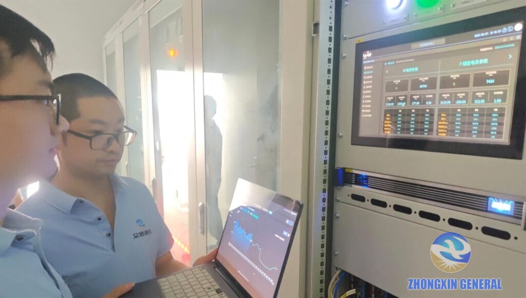
- Oil-Immersed Main Transformer: Equipped with oil chromatogram online monitoring, partial discharge monitoring, winding optical fiber temperature measurement, oil level temperature and pressure release state monitoring
- Dry-Type Transformer: Equipped with winding temperature inspection and partial discharge monitoring
- Communication Protocol: Support Modbus and IEC61850 protocols, access station monitoring platform to realize fault early warning and service life evaluation, reducing on-site inspection workload
8. High-Frequency Industry Selection Misunderstandings & Corrections
8.1 Misunderstanding 1: Prioritize Low Procurement Cost
Blindly selecting aluminum winding and Grade 3 energy efficiency old models ignores the 25-year full-life-cycle operation loss. The long-term power loss cost is far higher than the equipment price difference.Correction: Prioritize all-copper winding and Grade 2+ high energy efficiency transformers.
8.2 Misunderstanding 2: No Capacity Margin Reserved
Matching transformer capacity exactly with module/PCS rated power fails to adapt to PV 1.1-1.3 overconfiguration and energy storage bidirectional peak impact. Correction: Reserve 10%-30% capacity redundancy according to project type.
8.3 Misunderstanding 3: Universal Double-Winding for LC Filter Inverters
LC filter multi-inverter parallel is prone to circulation. Correction: Prioritize double-split transformers for LC filter schemes; double-winding transformers are applicable to LCL filter scenarios.
8.4 Misunderstanding 4: Apply PV Unidirectional Transformer to Energy Storage Projects
Ordinary PV transformers only support unidirectional power transmission and cannot adapt to energy storage bidirectional charge-discharge working conditions. Correction: Special bidirectional energy storage transformers must be adopted for energy storage stations.
8.5 Misunderstanding 5: Universal Plain Standard Equipment for All Environments
Directly using plain transformers for high-altitude, coastal and extreme cold projects leads to frequent insulation faults. Correction: Customize equipment according to environmental characteristics.
8.6 Misunderstanding 6: Adopt Yyn0 Wiring Group for New Energy Boosting
Yyn0 has poor harmonic suppression and unbalanced load resistance. Correction: New energy boost transformers uniformly adopt Dyn11/Dy11 wiring group.
9. Conclusion
Transformer selection for PV, wind and energy storage stations is a systematic comprehensive decision covering grid connection standards, power generation working conditions, environmental conditions, energy efficiency compliance and full-life-cycle cost, not a simple capacity and voltage check.
Core selection principles summary: Adopt dry-type transformers for indoor, energy storage cabin and densely populated scenarios; select oil-immersed transformers for deserts and large-scale outdoor stations; match double-split/double-winding transformers according to inverter filter schemes; reserve reasonable capacity margin, prioritize Dyn11 wiring group and all-copper winding; strictly implement national energy efficiency standards and eliminate backward low-efficiency models; customize equipment for extreme environments and configure intelligent monitoring for large boost stations.
In addition, transformer parameters such as short-circuit impedance, voltage tapping range and grounding mode must be consistent with the grid connection system report to ensure smooth grid connection and acceptance of the project. For professional new energy transformer customization and project supporting solutions, you can contact our professional technical team for one-to-one technical consultation.
Frequently Asked Questions About New Energy Transformer Selection
Q1: What is the difference between new energy transformer and traditional transformer?
New energy transformers adapt to intermittent power generation, frequent load fluctuation and high harmonic working conditions of PV, wind and energy storage systems, with higher harmonic resistance, bidirectional power transmission capacity and environmental adaptability, while traditional transformers only adapt to stable thermal power working conditions.
Q2: Which transformer is better for energy storage stations, dry-type or oil-immersed?
Dry-type transformers with fireproof and explosion-proof performance are preferred for indoor cabin energy storage stations; oil-immersed transformers with high cost performance and strong heat dissipation are suitable for large outdoor centralized energy storage boost stations.
Q3: What energy efficiency standard must new energy transformers comply with in 2026?
All new PV, wind and energy storage projects must comply with GB20052-2024 standard, with Grade 3 energy efficiency as the minimum threshold. Old models such as S11 and SCB10 are prohibited, and SCB18/S22 high-efficiency models are prioritized.
Q4: Why do energy storage transformers need larger capacity margin?
Energy storage systems have bidirectional charge-discharge peak impact, and the load fluctuation is more severe than that of PV and wind power. A 20%-30% capacity margin can effectively avoid overload operation and prolong equipment service life.
View our full range of new energy transformers and box substation products | Browse more new energy power industry technical guides and project cases